
Active drag and thrust modulation system and methods

a technology of active drag and thrust, applied in the field of vehicles, can solve the problems of increasing aerodynamic drag that requires greater power consumption, increasing pressure gradient, and insufficient maintenance of relatively low kinetic energy of air molecules closest to the airfoil surface, and achieve the effect of enhancing the atomization of the fuel spray

Inactive Publication Date: 2005-12-27
P TECH
View PDF33 Cites 37 Cited by
  • Summary
  • Abstract
  • Description
  • Claims
  • Application Information

AI Technical Summary

Benefits of technology

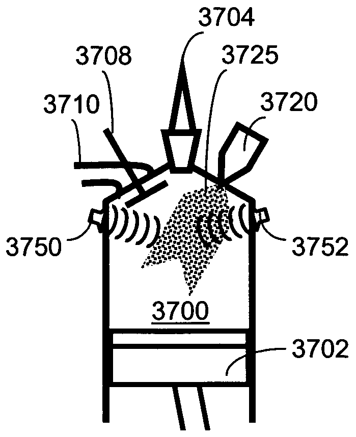
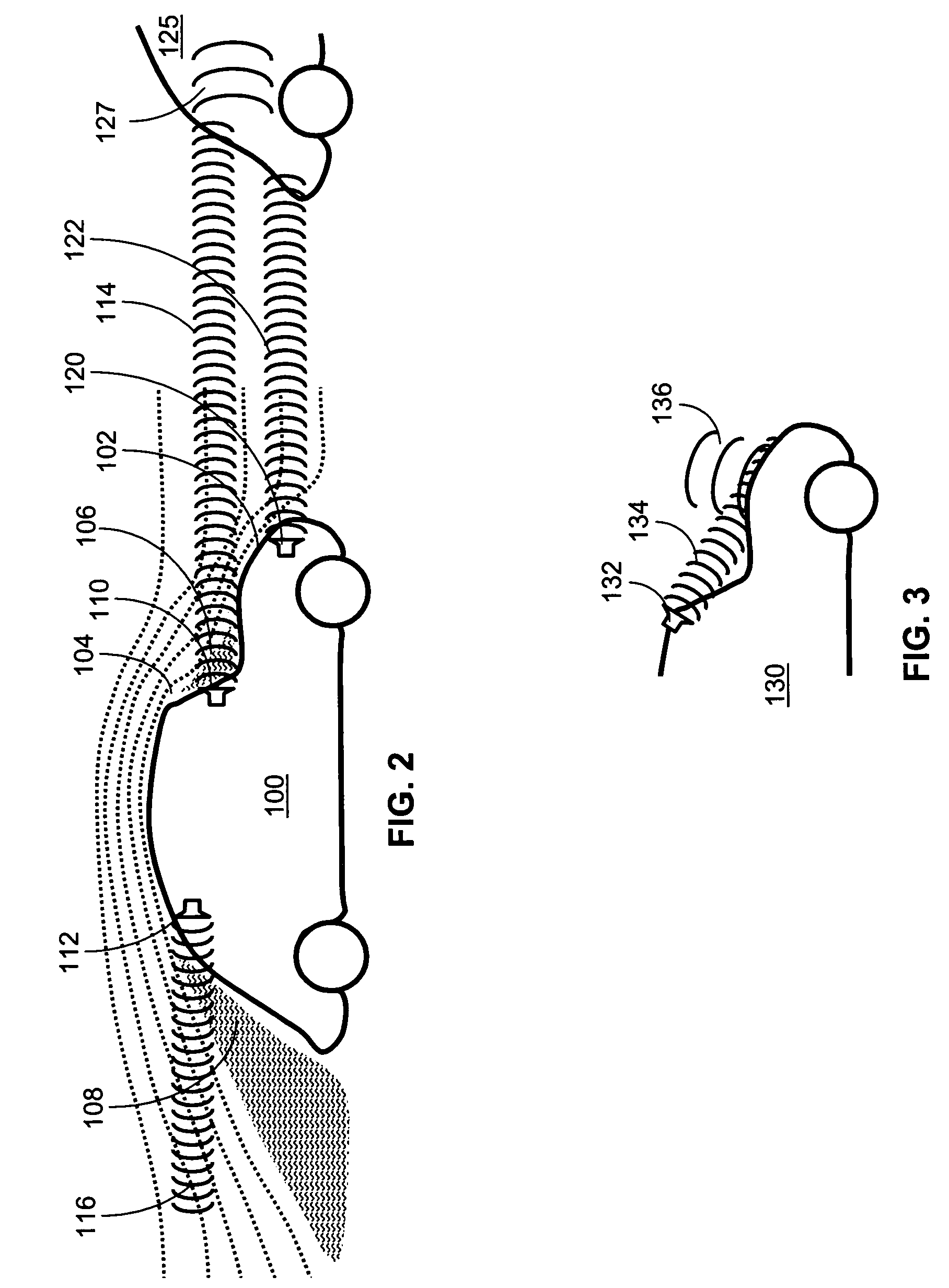
The present invention relates to a method and device for reducing drag and increasing efficiency of a vehicle or other object traveling through an environmental media such as air or water. This is achieved by transmitting energy beams or substances that modify the drag of the object. The invention also includes methods for compensating for drag in cross-directional movement and enhancing atomization of fuel spray. Additionally, the invention includes a method for selectively heating a vehicle tire and a device for transmitting ultrasonic signals and modulating them with an audio signal. Overall, the invention improves the performance and efficiency of objects traveling through environmental media.

Problems solved by technology

The increase in surface friction causes increased aerodynamic drag that requires greater power consumption to maintain constant airfoil speed.
Thereafter, the pressure gradient will increase and the relatively low kinetic energy of the air molecules closest to the airfoil surface may be insufficient to maintain laminar flow against the gradient.
The problem, then, is to develop means to control the boundary layer of an airfoil in order to reduce aerodynamic drag and the energy losses associated therewith.
While some aircraft have movable control surfaces that increase drag and lift, movable control surfaces on other vehicles such as automobiles or boats become impractical.
Movable control surfaces add considerable weight, cost and complexity to the design of a vehicle, which may nevertheless benefit from increases in drag in certain applications.
Aerodynamic drag may be increased by disrupting laminar flows with acoustic energy.
This disruption of laminar flow with acoustic energy thereby increases vehicle drag.
Ultrasonic transducers are tuned to operate efficiently in a relatively narrow frequency range and are typically precluded from being effective at generating frequencies low enough to be heard as audio signals.
Crosswind results in difficulty in controlling the flight of an aircraft and in providing a comfortable environment for aircraft passengers.
However, the sails of the multiple masts typically have identical surfaces which are not adapted to take advantage of the slipstream.
The thin sails of a sailing ship do not take full advantage of various aerodynamic flows at various operating conditions of the ship because the sails are thin.
Keels of sailing ships are typically fixed and unable to modify their hydrodynamic characteristics in response to various sailing conditions.
Furthermore, turbulent airflows prior to combustion can disadvantageously cause the fuel to separate from the air.
Warm tires have improved traction, but the traction comes at the expense of tread life.

Method used


Image

  • Active drag and thrust modulation system and methods
  • Active drag and thrust modulation system and methods
  • Active drag and thrust modulation system and methods

Examples


Embodiment Construction

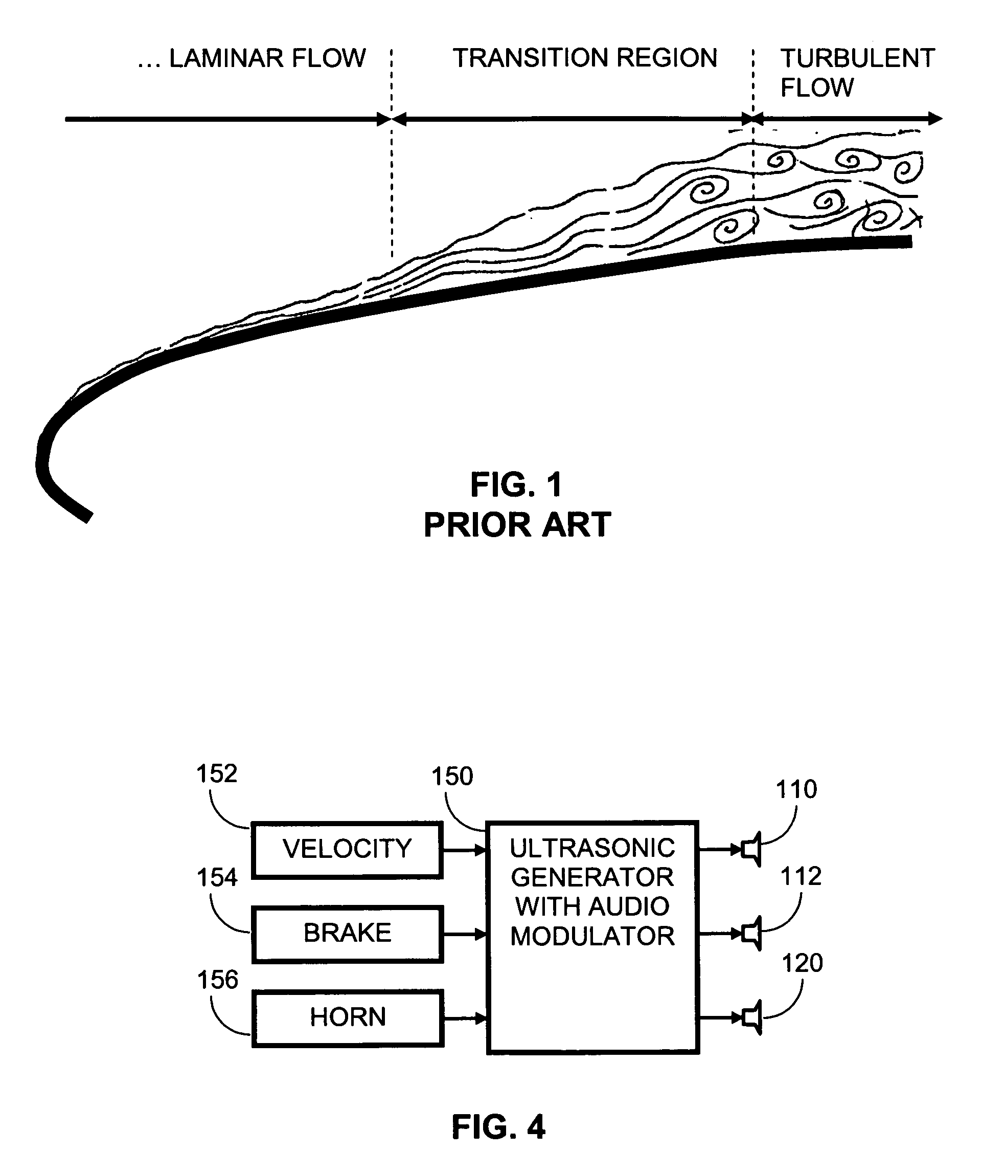
[0074]FIG. 1 illustrates a typical lifting aerodynamic surface having a laminar flow boundary layer. Thin laminar boundary layer flow is observed in the laminar flow region from the leading edge to a point at which transition begins. The beginning of the transition region is characterized by a thickening of the boundary layer and the appearance of small eddying perturbations in airstream velocity. As the airstream progresses through the transition region, certain airflow disturbances within a range of predictable oscillatory frequencies, known as Tollmien-Schlichting waves, become amplified to form eddies that cause a transfer of momentum from the higher energy air near the outer surface of the boundary layer to the low energy air at the surface. At this point the airstream enters the turbulent region, being comprised of many large eddies and characterized by a relatively higher average velocity near the airfoil surface. The higher velocity creates greater surface friction with the ...


PUM


Abstract

A vehicle traveling through an environmental media such as air experiences drag. The drag is actively modulated by energy beams which may either increase or decrease the drag. The energy beams may provide either a chemical, acoustic or electromagnetic energy at a transition region between turbulent and laminar flows or at the leading edge of a laminar flow or in the direction of a crosswind in order to facilitate the respective increase or decrease in drag. If the vehicle is a sailing ship, areas of the sails are selectively roughened or widened to enhance the thrust derived from the wind. Furthermore, the keel or hull of the sailing ship may be modified to improve the hydrodynamic characteristics of the sailing ship. If the vehicle is an automobile, the tires or road surface may be selectively heated to improve the traction of the automobile. Furthermore, the energy beams may be used to facilitate atomization of the air / fuel mixture prior to combustion in an internal combustion engine thereby improving the thrust of provided to the vehicle. Energy beams may be used to generate virtual extensions of a vehicle to enhance traveling efficiency.

Description

CROSS-REFERENCE TO RELATED APPLICATION[0001]This is a divisional of U.S. patent application Ser. No. 10 / 386,992 entitled Active Drag and Thrust Modulation System and Methods filed Mar. 12, 2003, now U.S. Pat. No. 6,793,177 which is a continuation in part of U.S. patent application Ser. No. 10 / 287,379 entitled Active Drag Modulation System and Method filed Nov. 4, 2002 now U.S. Pat. No. 6,824,108.FIELD OF THE INVENTION[0002]This invention relates to the field of vehicles utilizing thrust and experiencing drag traveling through an environmental media, and more particularly the modification of thrust, turbulence and drag.BACKGROUND OF THE INVENTION[0003]Supercavitation occurs when an object moving through water reaches speeds in excess of 100 knots. At this speed it is possible for a bubble of air to form around the object, beginning at the nose of the object. The bubble can extend completely around the entire object and hence the object is no longer moving through the water, rather th...

Claims


Application Information

Patent Timeline
Patent Type & Authority Patents(United States)
IPC IPC(8): B62D35/00B63B1/34B63H9/06B64C23/00F02M29/00F02M51/00F02M69/04F15D1/12
CPCB60C19/00B62D35/00B63B1/34B63H9/04B63H9/06B64C23/005F02M27/08F02M69/041F15D1/12F15D1/0075B63B2039/068F02B2075/125Y02T50/166Y02T70/121Y02T70/583Y02T10/123B64C2230/02Y10T137/206Y10T137/0391Y10T137/2191Y02T10/12Y02T50/10Y02T70/10Y02T70/5236
Inventor BONUTTI, PETER M.
Owner P TECH
Learn More