
Soot burn-off control strategy for a catalyzed diesel particulate filter

a technology of diesel particulate filter and burn-off control, which is applied in the direction of electrical control, exhaust treatment electric control, separation process, etc., can solve the problems of osub>2/sub>more difficult to treat diesel engine exhaust without, and increase the cost of the exhaust treatment system

Inactive Publication Date: 2005-12-27
INT ENGINE INTPROP CO LLC
View PDF7 Cites 50 Cited by
  • Summary
  • Abstract
  • Description
  • Claims
  • Application Information

AI Technical Summary

Benefits of technology

The present invention relates to a method and system for regenerating a CDPF (diesel particulate filter) in an engine. The invention uses data from the engine control system to initiate regeneration either regularly or when conditions are favorable, and to terminate regeneration when conditions no longer favor it. This can improve engine and vehicle performance by reducing the amount of trapped soot in the CDPF and lowering back-pressure on the engine. The invention can be easily integrated into existing engine control systems and can be used in vehicles propelled by the engine.

Problems solved by technology

Such limitations hinder a more widespread use that is obviously desirable in order to maximize the benefit of DPF technology in motor vehicles.
While O2 could be used to oxidize DPM, the high temperatures needed for oxidation make O2 more difficult for treating diesel engine exhaust without the aid of still another catalyst such as cerium-oxide (CeO2).
The inclusion of a second catalyst separate from the DPF adds to the cost of the exhaust treatment system.
That factor makes natural achievement of BPT problematic.

Method used


Image

  • Soot burn-off control strategy for a catalyzed diesel particulate filter
  • Soot burn-off control strategy for a catalyzed diesel particulate filter
  • Soot burn-off control strategy for a catalyzed diesel particulate filter

Examples


Embodiment Construction

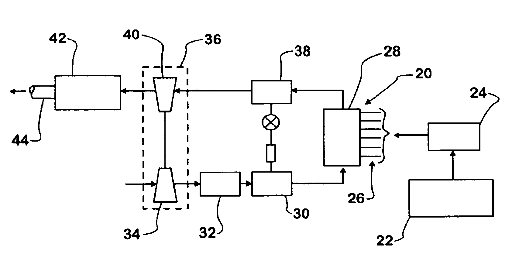
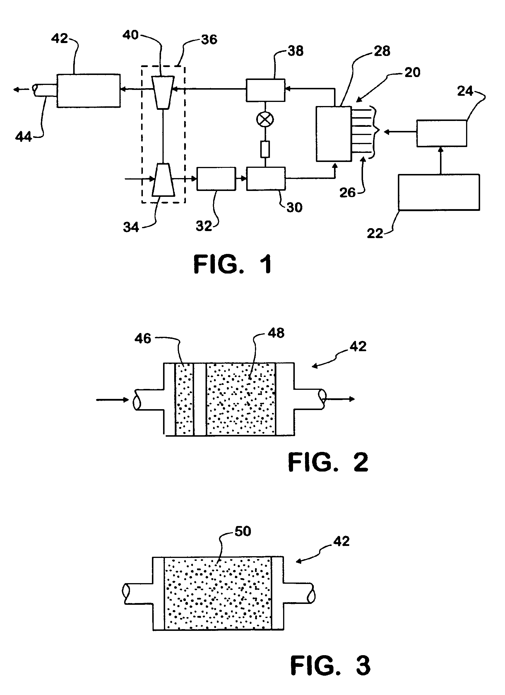
[0025]FIG. 1 shows a schematic diagram of an exemplary diesel engine 20 for powering a motor vehicle. Engine 20 has a processor-based engine control system 22 that processes data from various sources to develop various control data for controlling various aspects of engine operation. The data processed by control system 22 may originate at external sources, such as sensors, and / or be generated internally.

[0026]Control system 22 includes an injector driver module 24 for controlling the operation of electric-actuated fuel injectors 26 that inject fuel into combustion chambers in the engine cylinder block 28. A respective fuel injector 26 is associated with each cylinder and comprises a body that is mounted on the engine and has a nozzle through which fuel is injected into the corresponding engine cylinder. A processor of engine control system 22 can process data sufficiently fast to calculate, in real time, the timing and duration of injector actuation to set both the timing and the a...


PUM


Abstract

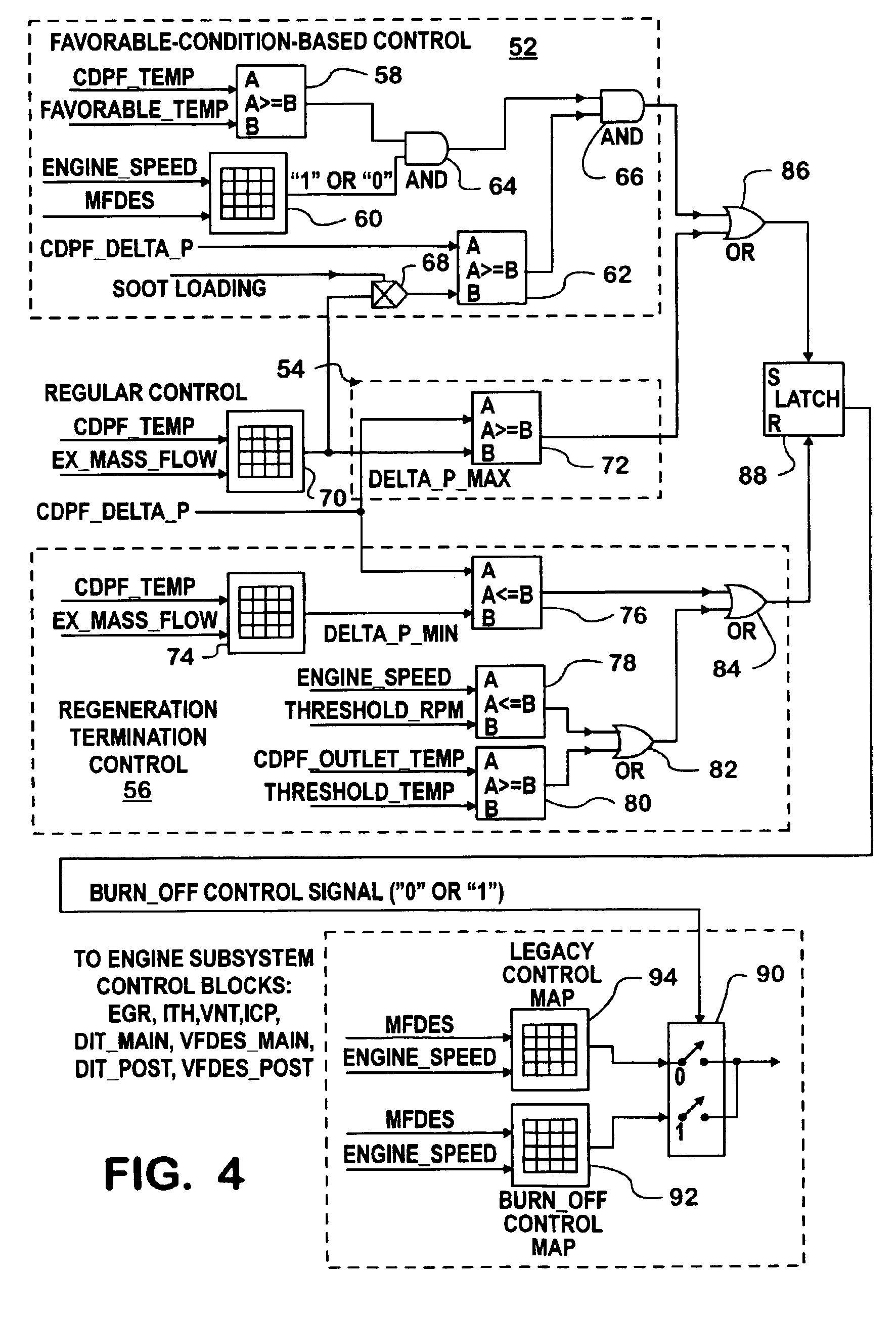
A control system (FIG. 4) for controlling regeneration of a DPF comprises a favorable-condition-based control section (52), a regular control section (54), and a regeneration termination control section (56). Section (54) initiates regeneration when the actual soot loading of the DPF becomes sufficiently large to mandate initiation of regeneration. Section (52) initiates regeneration when the actual soot loading reaches an amount less than the amount at which section (54) mandates regeneration, provided that selected engine operating conditions disclose conditions favorable for regeneration. Section (56) terminates regeneration when soot loading is reduced to some minimum amount or when conditions for continuing regeneration become unfavorable. By burning trapped soot during favorable conditions, the mandatory regeneration is postponed. This can lower the average amount of trapped soot in the CDPF, thereby lowering the average back-pressure on the engine.

Description

FIELD OF THE INVENTION[0001]This invention relates generally to diesel engines that have diesel particulate filters for treating exhaust gases passing through their exhaust systems. More particularly, the invention relates to engine systems and methods for controlling the burning of soot trapped by a catalyzed diesel particulate filter (CDPF).BACKGROUND OF THE INVENTION[0002]An exhaust system of a diesel engine that comprises a diesel particulate filter (DPF) is capable of physically trapping diesel particulate matter (DPM) in exhaust gas passing through the exhaust system from the engine. DPM includes soot or carbon, the soluble organic fraction (SOF), and ash (i.e. lube oil additives etc.). The trapping of those constituents by a DPF reduces the amount of DPM entering the atmosphere, preventing what is sometimes seen as black smoke billowing from a vehicle's exhaust pipe.[0003]When a DPF is present in the exhaust system of a motor vehicle powered by a diesel engine, it is desirabl...

Claims


Application Information

Patent Timeline
Patent Type & Authority Patents(United States)
IPC IPC(8): B01DF01N3/00F01N3/023F01N13/02F02B37/00F02D41/00F02D41/02
CPCF01N3/023F02D41/029F01N13/0097F02B37/00F02D41/0007F02D2200/0812Y02T10/40F01N3/00F01N9/00F01N3/02
Inventor WANG, XINLEIGUI, XINQUNREN, SHOUXIANZHANG, GUOQING
Owner INT ENGINE INTPROP CO LLC
Learn More