
Optical network architecture

a network architecture and optical network technology, applied in the field of optical communication networks, can solve the problems of no protection, high cost of ring topology metro access network, and increased cost of arrangemen

Inactive Publication Date: 2005-12-20
RPX CLEARINGHOUSE
View PDF9 Cites 4 Cited by
  • Summary
  • Abstract
  • Description
  • Claims
  • Application Information

AI Technical Summary

Benefits of technology

[0004]It is an object of the present invention to provide an improved or at least alternative optical network architecture. It is a fu...

Problems solved by technology

This arrangement is more expensive as it requires additional fibre and switching complexity, but provides the protection required where large numbers of calls would otherwise be affected.
Currently the high cost of ring topology metro access networks is hampering deployment in this network space.
However tree architectures, while cheaper to deploy, offer no protection and are therefore unsuitable for metro access networks.
Filters tend to be expensive and also relatively high loss thereby reducing the maximum diameter of the ring in a passive network.

Method used


Image

  • Optical network architecture
  • Optical network architecture
  • Optical network architecture

Examples


Embodiment Construction

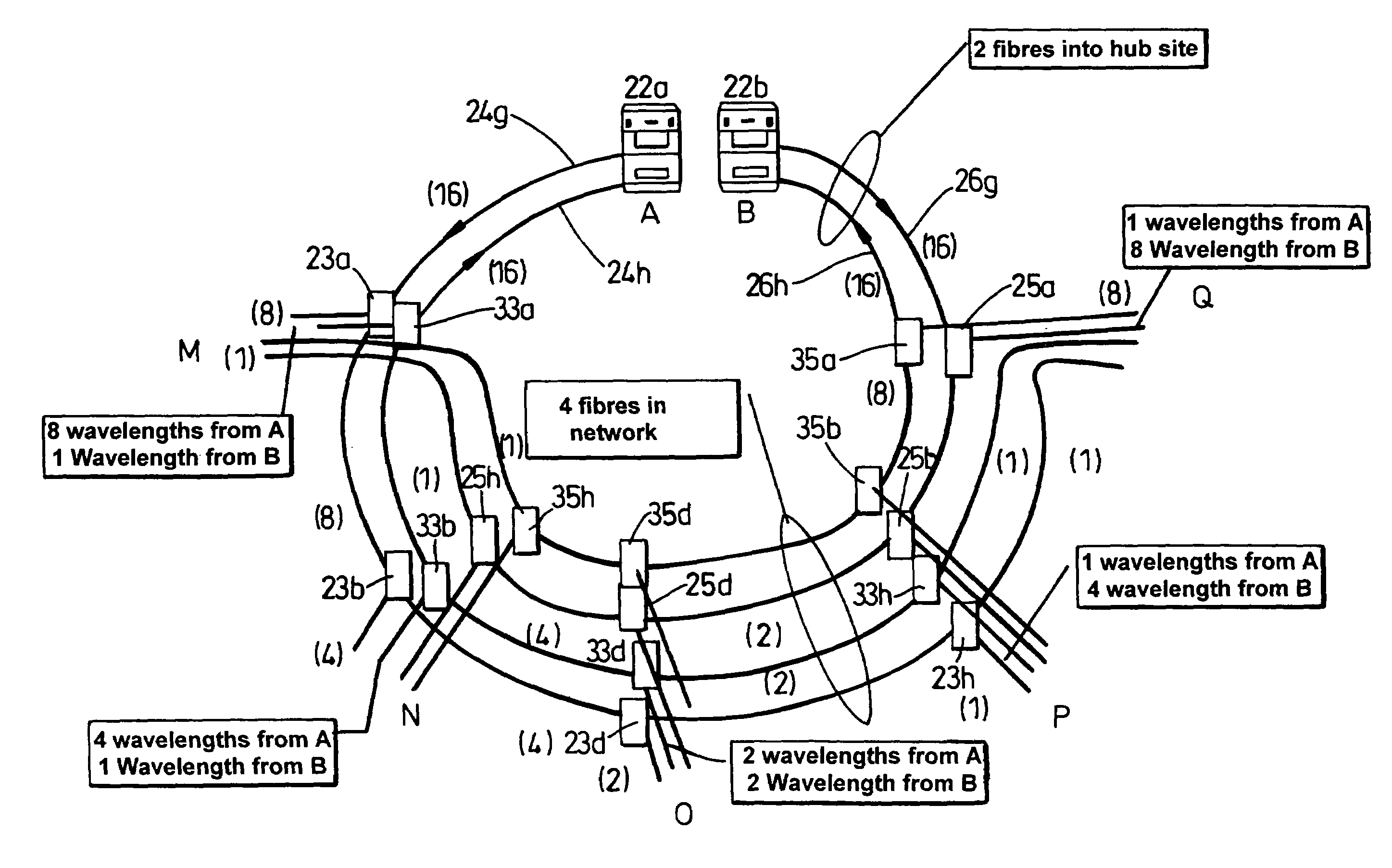
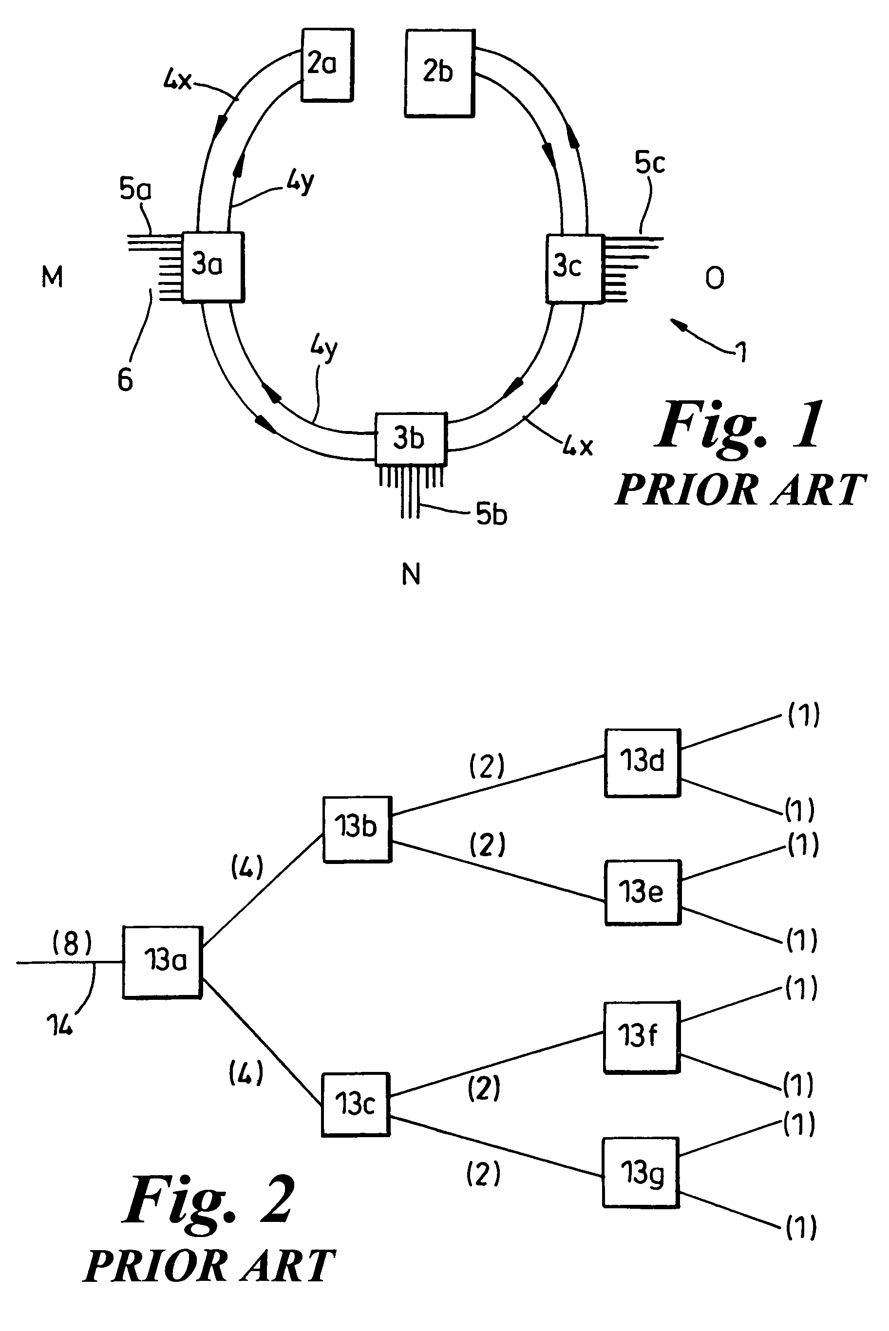
[0022]FIG. 1 shows a prior art optical broadband coupler network 1 arranged into a ring architecture. The network comprises two headends, exchanges or central offices 2a and 2b which direct signals around the ring comprising optical fibre 4 and filter elements 3. The headends 2a and 2b send and receive signals on predertermined channels on the optical fibre 4 of the network 1. The headends 2a and 2b co-operate and couple the network 1 to an external network such as a backbone or carrier network for example. Where the headends 2a and 2b are co-located they effectively operate as a single logical headend unit 2. In the example of FIG. 1, a first fibre ring 4x carries a number of channels in a WDM transmission system, the signals going via filter elements 3a, 3b, and 3c respectively and onto the second headend 2b. A second fibre ring 4y is included from headend 2b via filter elements 3c, 3b and 3a, and onto headend 2a. In practice the first ring 4x and the second ring 4y are implemente...


PUM


Abstract

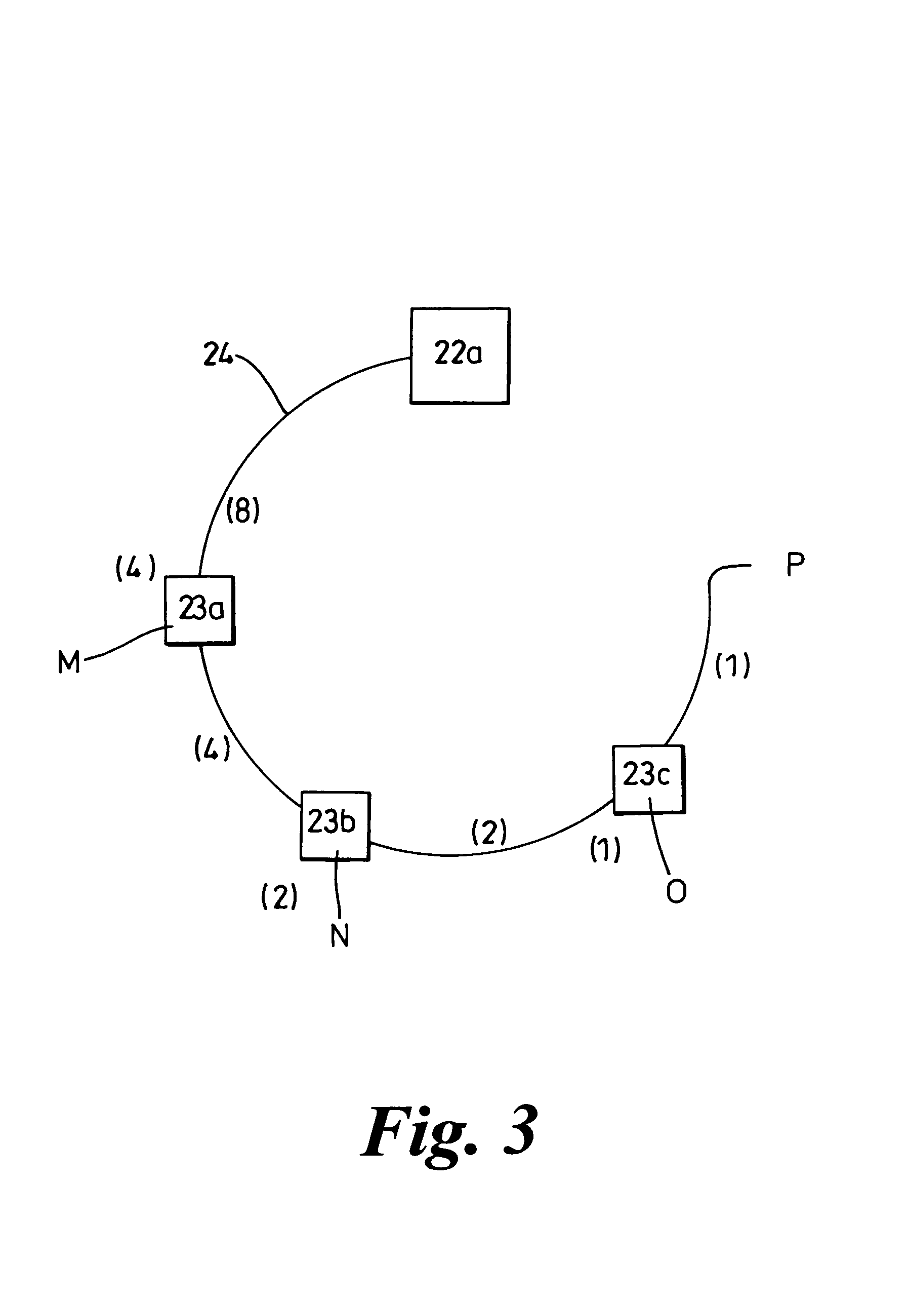
A communications network having two complementary optical networks each connectable to a headend, each optical network comprising a plurality of periodic interleaving filters serially connected by optical waveguides such that an output port of one periodic interleaving filter is couple to an input port of another periodic interleaving filter, and wherein an input or output node of the network is formed by a non-serially connected input or output port of a periodic interleaving filter.

Description

FIELD OF THE INVENTION[0001]The present invention relates to optical communications networks, and particularly though not exclusively to an optical network ring topology especially suitable for metro access.BACKGROUND OF THE INVENTION[0002]Optical communications networks are typically arranged into either tree or ring architectures. Both architectures are well known and are generally employed in different circumstances. Ring architectures are typically employed in long haul or trunk routes where circuit protection is important. Because the network is arranged into a ring, a break in the ring fibre can be overcome by re-routing traffic around the ring in the opposite direction. This arrangement is more expensive as it requires additional fibre and switching complexity, but provides the protection required where large numbers of calls would otherwise be affected. Tree architectures are also well known and tend to be used in access networks where protection is less critical and reduced...

Claims


Application Information

Patent Timeline
IPC IPC(8): H04B10/20H04B10/213H04B10/272
CPCH04B10/271H04B10/2755
Inventor FORBES, DUNCAN JDYKE, PETERDYER, MICHAEL P
Owner RPX CLEARINGHOUSE
Learn More