
Differential phase detection device and tracking error signal detection apparatus using the same

a detection device and detection apparatus technology, applied in the direction of instrumentation, phase-modulated carrier systems, transmission monitoring, etc., can solve the problem of consuming a large amount of power, and achieve the effect of improving the structure of employing

Inactive Publication Date: 2005-12-20
SAMSUNG ELECTRONICS CO LTD
View PDF11 Cites 14 Cited by
  • Summary
  • Abstract
  • Description
  • Claims
  • Application Information

AI Technical Summary

Benefits of technology

[0013]To solve the above problems, the present invention to provides a differential phase detection device having an improved structure for employing a single phase difference detector without using a delay unit and a tracking error signal detection apparatus using the same.

Problems solved by technology

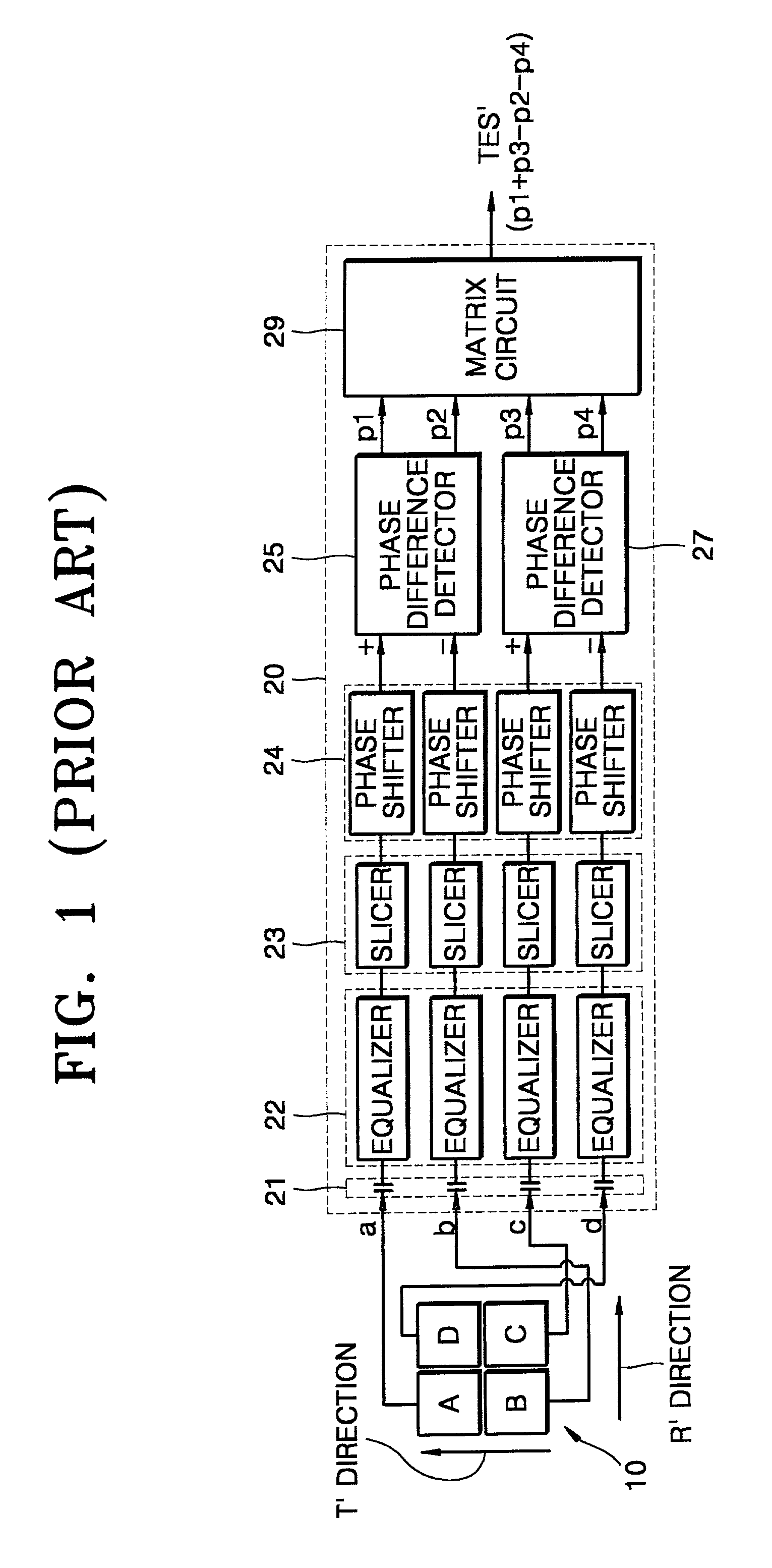
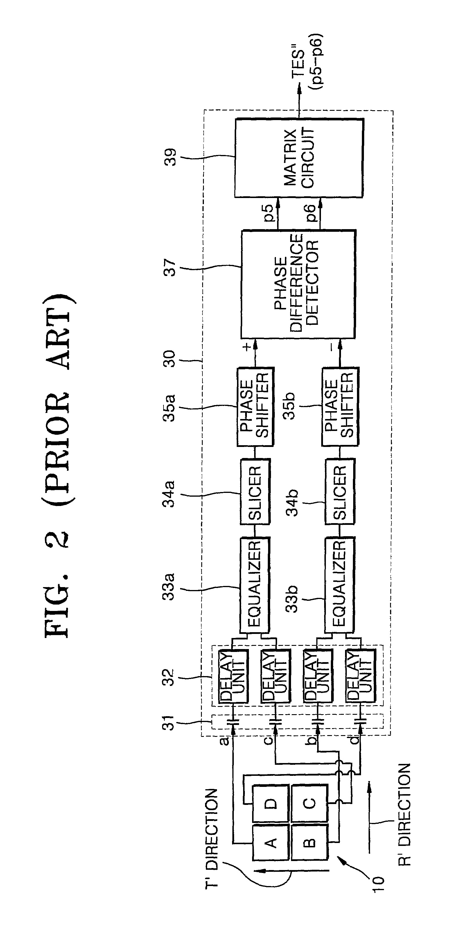
Consequently, the differential phase detection device 30 of FIG. 2 has a larger volume than the differential phase detection device 20 of FIG. 1 and consumes a larger amount of power.

Method used


Image

  • Differential phase detection device and tracking error signal detection apparatus using the same
  • Differential phase detection device and tracking error signal detection apparatus using the same
  • Differential phase detection device and tracking error signal detection apparatus using the same

Examples


Embodiment Construction

[0040]FIG. 3 is a schematic block diagram illustrating an embodiment of a tracking error signal detection apparatus using a differential phase detection device according to the present invention. Referring to FIG. 3, the tracking error signal detection apparatus includes a photodetector 50 for receiving light reflected from a recording medium and a differential phase detection device 70 for detecting a differential phase from detection signals a, b, c and d output from the photodetector 50.

[0041]The photodetector 50 includes first through fourth division plates A, B, C and D in R′ and T′ directions counterclockwise (or clockwise). The first and third division plates A and C are positioned in one diagonal line, and the second and fourth division plates B and D are positioned in another diagonal line. The first through fourth detection signals a, b, c and d output from the first through fourth division plates A, B, C and D, respectively, are input to the differential phase detection d...


PUM


Abstract

A differential phase detection device receives first through fourth detection signals from a photodetector and detects a differential phase signal therefrom, the differential phase detection device includes a slicer slicing and digitizing each of the detection signals with respect to a reference level. A synthesizer synthesizes the digitized detection signals and generates therefrom synthesis signals. A phase difference detector compares phases of the synthesis signals and outputs a first phase difference signal and a second phase difference signal. A matrix circuit processes the first and second phase difference signals to output the differential phase signal.

Description

CROSS-REFERENCE TO RELATED APPLICATIONS[0001]This application claims the benefit of Korean Application No. 2000-82052, filed Dec. 26, 2000, in the Korean Industrial Property Office, the disclosure of which is incorporated herein by reference.BACKGROUND OF THE INVENTION[0002]1. Field of the Invention[0003]The present invention relates to a differential phase detection device having an improved structure and a tracking error signal detection apparatus using the same.[0004]2. Description of the Related Art[0005]Generally, as shown in FIGS. 1 and 2, a tracking error signal detection apparatus using a differential phase detection (DPD) device includes a four-division photodetector 10 for receiving light reflected from a recording medium, and differential phase detection devices 20 and 30 for receiving four detection signals a, b, c, and d output from the four-division photodetector 10, generating a plurality of phase difference signals P1, P2, P3, P4, P5, and P6, and performing an operat...

Claims


Application Information

Patent Timeline
IPC IPC(8): G11B7/09G11B7/08
CPCG11B7/0906G11B7/094G11B7/08
Inventor MA, BYUNG-INPARK, IN-SIKSEO, JOONG-EONGO, SUNG-ROJUNG, SOO-YULYANG, CHANG-JIN
Owner SAMSUNG ELECTRONICS CO LTD
Learn More