Dual mode switch mechanism for flashlights

Active Publication Date: 2005-12-20
NITE IZE
View PDF107 Cites 17 Cited by
  • Summary
  • Abstract
  • Description
  • Claims
  • Application Information

AI Technical Summary

Benefits of technology

[0007]In this regard, and in furtherance of the above stated objectives, the present invention provides a unique dual mode, inline switch mechanism that is fully integrated into the rear cap of a flashlight assembly to provide a completely self contained and waterproof switching mechanism. The switch assembly further provides a reliable OFF position that prevents the accidental activation of the light when the user desires that it remain off.
[0009]By limiting the travel of the plunger and contact plate to a predictable distance, the present invention can achieve the desired multifunctionality, namely, a momentary ON function, a full ON function and a verifiable OFF function. Each one of the functions is selected by rotating the end cap assembly including the switch of the present invention. As the end cap of the assembly is rotated, its linear spacing relative to the flashlight housing is increased or decreased thereby altering the mode of switch operation. In this manner an economical flashlight assembly is provided that has a reduced number of operational parts as compared to the prior art thereby producing a more reliable product.
[0010]The switch in the end cap further operates in conjunction with the spring element located in the head of the flashlight to further insure retention of the batteries and a positive electrical contact between the batteries and the head assembly. Further, the spring bias caused by the spring assembly in the head of the flashlight causes the batteries to be pressed rearwardly, which in turn causes the contact plate and plunger to be urged rearwardly creating the normally open bias for the switch assembly.
[0011]In an alternate embodiment, the switching function related to the momentary ON position and the constant ON position are accomplished within the structure of the end cap using a ratcheting cam lock mechanism. In this embodiment, the contact plate remains in full contact with the end of the housing and the battery. A combination of contacts within the structure of the cap are then operable to active the light using the pushbutton. The constant OFF position is achieved by slightly unthreading the end cap from the flashlight housing until the contact plate is moved out of contact with the housing thereby breaking the path of the circuit and preventing the light from being energized.
[0012]Accordingly, one of the objects of the present invention is the provision of a low cost flashlight having a superior dual mode switching mechanism. Another object of the present invention is the provision of a flashlight having a dual mode switching mechanism that includes a momentary ON, a full ON and a verifiable OFF position. A further object of the present invention is the provision of a flashlight having a dual mode switch that includes a reduced number of moving components thereby reducing manufacturing and assembly costs while improving the reliability of the assembly. Yet a further object of the present invention is the provision of a flashlight assembly having a dual mode switch that is integrated in an inline fashion and is waterproof.

Problems solved by technology

One drawback is that the increased number of parts creates additional assembly steps and increases the difficulty of assembly process.
Another drawback is that when a flashlight of this type is stored in luggage, it is susceptible to being compressed by items that may shift during transit, thereby activating the flashlight and draining the battery.
A further drawback associated with this possibility of accidental activation is evident in high intensity flashlights that generate a great deal of heat during operation.
If a flashlight of this type is tightly packed in luggage and accidentally activated, it may cause a fire.
A number of such prior art designs feature rotatable end caps which are rotated to move the batteries longitudinally within the flashlight body towards the lamp bulb, thereby causing contact between the battery contact and the base contact of the lamp bulb.
While these switch mechanisms are internal to the device and thus less subject to damage, they are overly complicated in design thereby requiring higher assembly tolerances, which result in making them more costly to manufacture.

Method used


Image

  • Dual mode switch mechanism for flashlights
  • Dual mode switch mechanism for flashlights
  • Dual mode switch mechanism for flashlights

Examples


Embodiment Construction

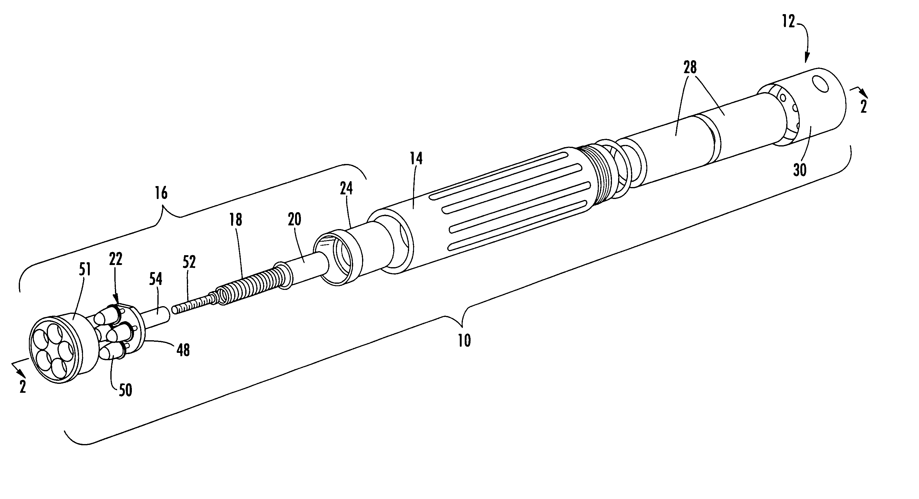
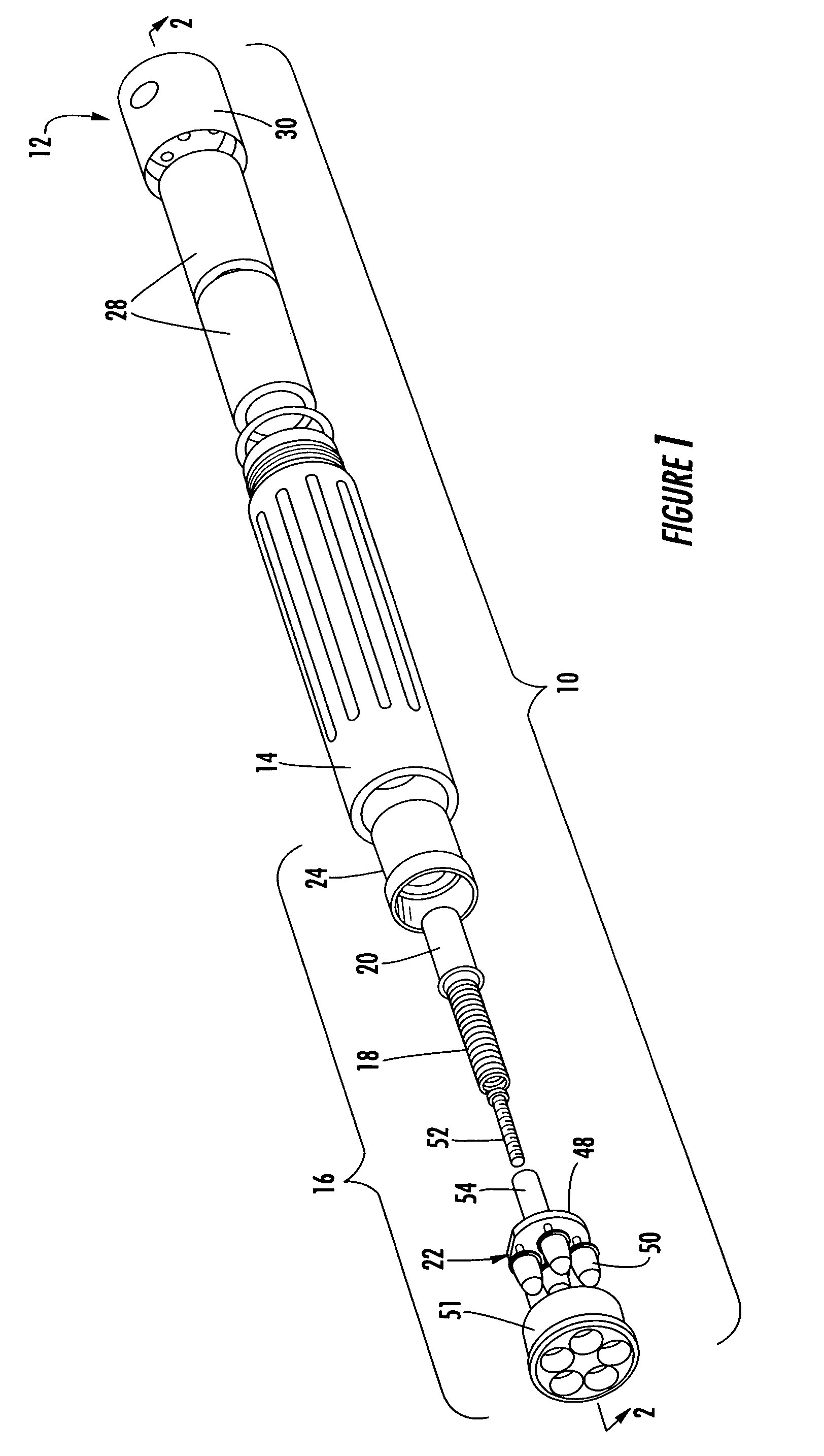
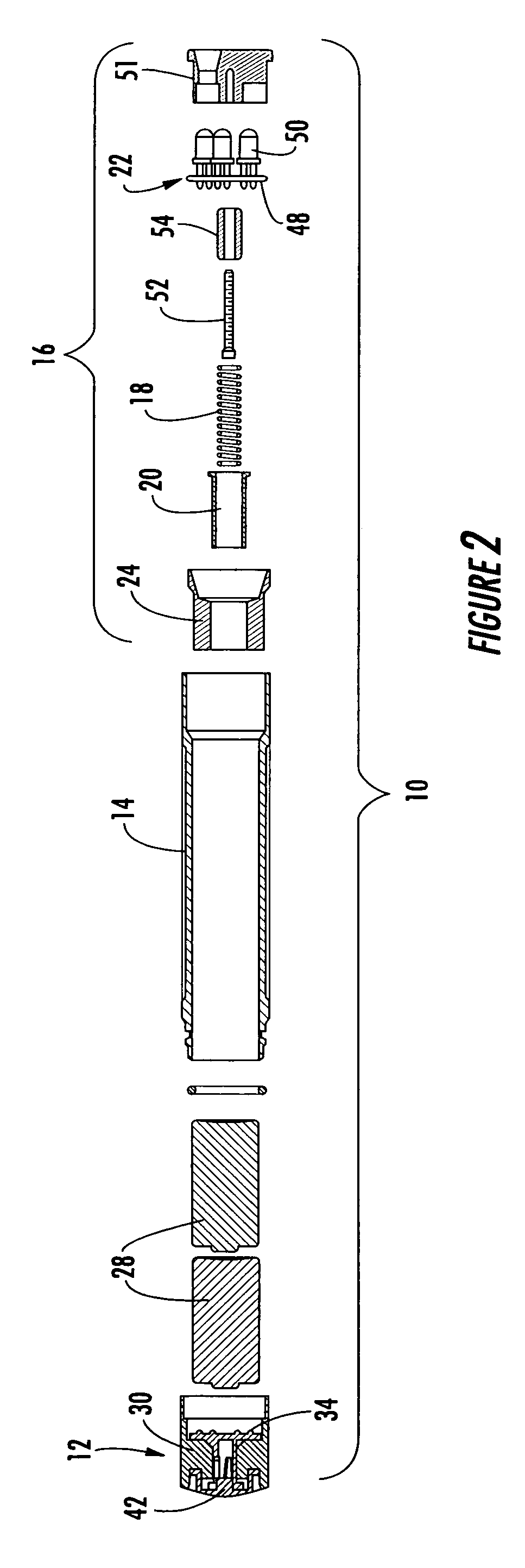
[0026]Referring now to the drawings, a flashlight assembly including an end cap with the dual mode switch of the present invention is illustrated and generally indicated at 10 in FIGS. 1–7. In accordance with the present invention, an in-line flashlight 10 is provided having a momentary ON, full ON and confirmable OFF position. The flashlight 10 has three major components including an end cap 12, an outer housing 14 and a head assembly 16. When fully assembled the components interface with one another for form a novel and useful flashlight 10 that has previously been unknown in the art.

[0027]Turning to FIGS. 1 and 2 as a general overview, the flashlight 10 of the present invention has an outer housing 14 that is preferably electrically conductive, however, a circuit trace or contact wire may be installed in the outer housing 14 to serve as a path of conductivity in lieu of the outer housing 14. The head assembly 16 is press fit into one end of the housing 14 and the end cap 12 is th...


PUM


Abstract

The present invention provides a unique dual mode, inline switch mechanism that is fully integrated into the rear cap of a flashlight assembly to provide a completely self contained and waterproof switching mechanism. The switch assembly further provides dual mode functionality including an ON position and a momentary ON position while also including a reliable OFF position that prevents the accidental activation of the light when the user desires that it remain off. The entire mechanism resides in the end cap of the flashlight assembly and includes an end cap structure that is designed to be rotatably attached to the end of a flashlight housing, a tactile ratchet lock assembly similar to a ballpoint pen, a plunger and an elastomeric cover. The switch mechanism is fully integrated on the interior of the flashlight providing the highly desirable, fully contained, in line functionality.

Description

CROSS-REFERENCE TO RELATED APPLICATIONS[0001]This application is a continuation-in-part of U.S. patent application Ser. No. 10 / 378,538, filed Mar. 3, 2003, now U.S. Pat. No. 6,709,129, which claims priority from earlier filed provisional patent application No. 60 / 373,464, filed Apr. 18, 2002.BACKGROUND OF THE INVENTION[0002]The present invention relates generally to a dual mode switch for improved functioning in flashlight devices. More specifically, the present invention relates to an improved pushbutton switching mechanism for flashlights that provides a momentary and constant ON feature as well as a positive, reliable OFF position.[0003]Flashlights of varying sizes and shapes are generally well known in the art. A number of such designs are known that utilize two or more batteries as their source for electrical energy. Typically, these batteries are carried in series in a tubular body, where the tubular body also serves as a handle for the flashlight. In order to operate the flas...

Claims


Application Information

Patent Timeline
IPC IPC(8): F21L4/02F21V23/04
CPCF21L4/027F21V23/0414F21Y2101/02F21Y2115/10
Inventor GALLI, ROBERT
Owner NITE IZE
Why Eureka
Try Eureka