
Spray cooling system for extreme environments

a cooling system and extreme environment technology, applied in indirect heat exchangers, semiconductor/solid-state device details, lighting and heating apparatus, etc., can solve the problems of increasing weight, not providing a method to increase the temperature of electronic components to the desired operating temperature, and inducing harmful external elements into the electronics enclosure. , to achieve the effect of short tim

Active Publication Date: 2005-12-20
PARKER INTANGIBLES LLC
View PDF71 Cites 32 Cited by
  • Summary
  • Abstract
  • Description
  • Claims
  • Application Information

AI Technical Summary

Benefits of technology

The technical effect described by this patented technology relating to a small but durable device called Spray Cooler (SC) can be used at extremely high temperatures without being affected or damaging it too much during its use. It also prevents damage caused by outside factors like radiation exposure while still allowing effective cooling when needed. Additionally, there are other features such as prevention against electrical arcs and fire hazards associated with these systems.

Problems solved by technology

The technical problem addressed in this patent is the need for a thermal management system that can maintain a safe and efficient internal operating environment for electronic components in extreme external environments, such as extreme temperatures, hostile elements, and extreme external environments. The current conventional thermal management systems, such as air-cooled enclosures and conduction cooling, have limitations and drawbacks, such as increased weight, size, and expense, and do not provide flexibility and increased performance. The spray cooling technology described in the patent provides a solution to this problem by providing an enclosed unit that can maintain a desirable internal temperature over an extreme external temperature range.

Method used


Image

  • Spray cooling system for extreme environments
  • Spray cooling system for extreme environments
  • Spray cooling system for extreme environments

Examples


Embodiment Construction

A. Overview

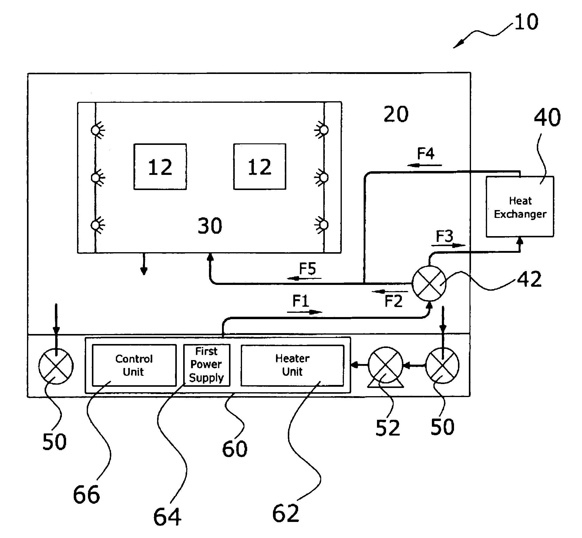
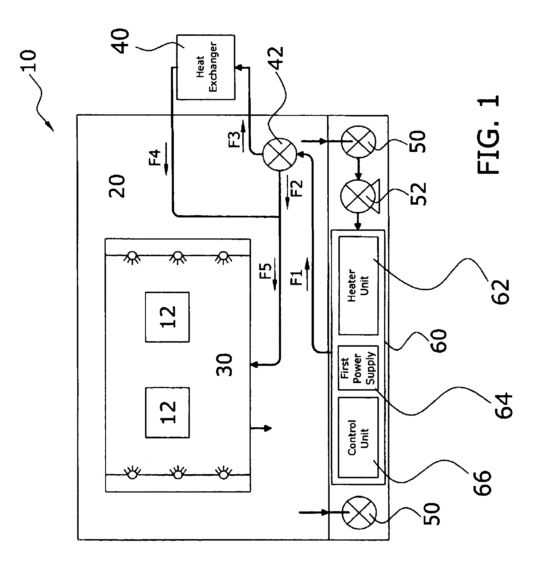
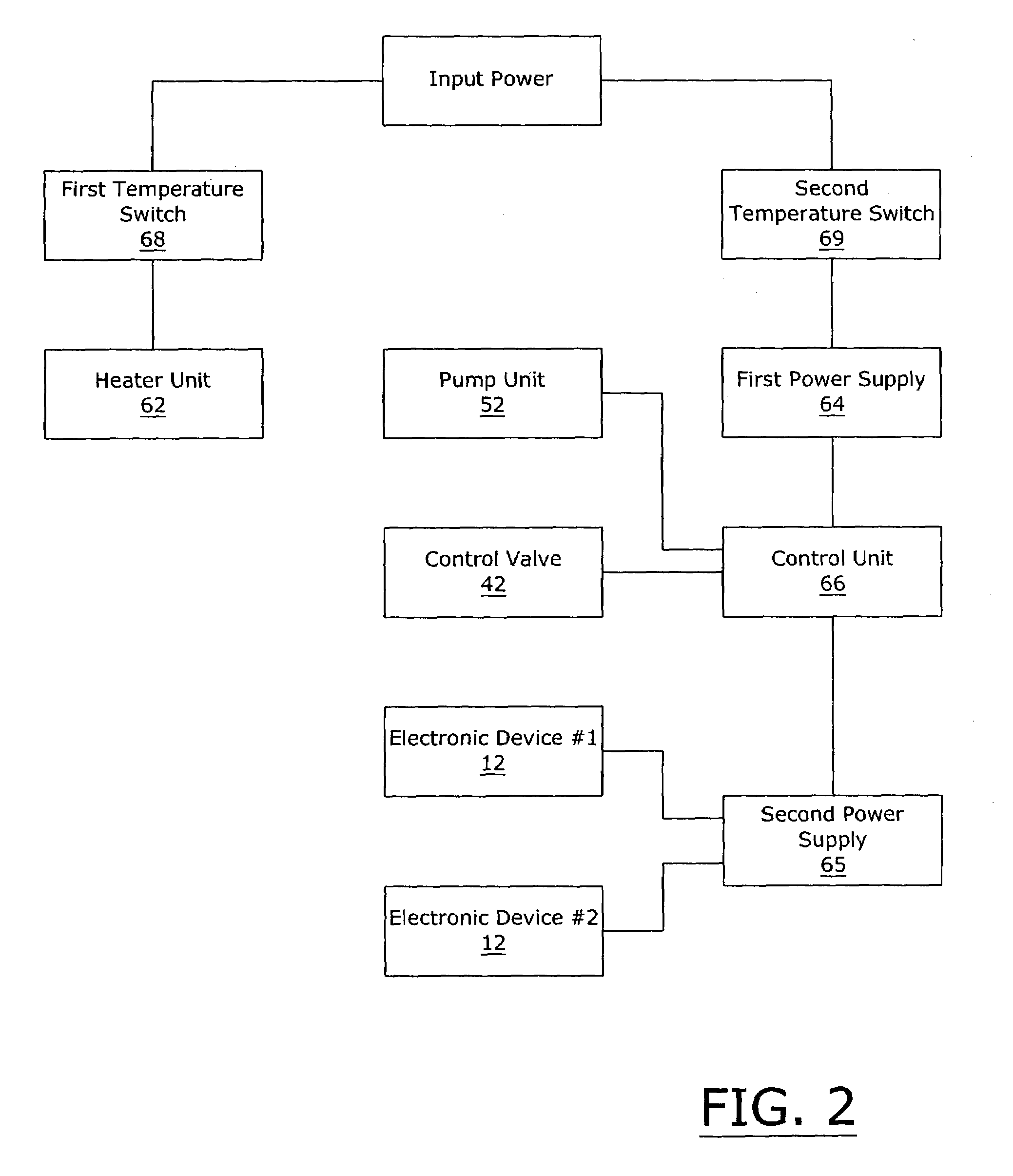
[0039]Turning now descriptively to the drawings, in which similar reference characters denote similar elements throughout the several views, FIGS. 1 through 5 illustrate a spray cooling system for extreme environments 10, which comprises an enclosure 20 that isolates the electronic components from the external environment, a spray unit 30 within the enclosure 20 for thermally managing one or more electronic devices 12, a pump unit 52 fluidly connected to the spray unit 30, a heat exchanger unit 40 fluidly connected to the pump, and a control valve 42 fluidly connected between the heat exchanger unit 40 and the pump. An independent chamber 60 preferably houses a heater unit 62, a first power supply 64 and a control unit 66, whereby the heater unit 62 initially heats the coolant within the independent chamber 60 to a minimum operating temperature prior to operation of the electronic components. The present invention may be utilized in various extreme environmental condition...


PUM


Abstract

A spray cooling system for extreme environments for providing a desired enclosed environment for electronic devices regardless of external environmental conditions. The spray cooling system for extreme environments includes an enclosure that isolates the electronic components from the external environment, a spray unit within the enclosure for thermally managing one or more electronic devices, a pump unit fluidly connected to the spray unit, a heat exchanger unit fluidly connected to the pump, and a control valve fluidly connected between the heat exchanger unit and the pump. An independent chamber preferably houses a heater unit, a first power supply and a control unit, whereby the heater unit initially heats the coolant within the independent chamber to a minimum operating temperature prior to operation of the electronic components.

Description


Claims


Application Information

Patent Timeline
Owner PARKER INTANGIBLES LLC
Learn More