
Vacuum variable capacitor with energization and heat shielding bellows

a vacuum variable capacitor and energizing technology, applied in the direction of mechanically variable capacitor details, capacitors with temperature varied dielectrics, non-mechanically variable capacitors, etc., can solve the problems of affecting affecting the slide ability of the slide portion, and the solution does not produce an effect, etc., to achieve the effect of reducing the life of vacuum variable capacitors and degrading the slideability

Active Publication Date: 2005-12-13
MEIDENSHA ELECTRIC MFG CO LTD
View PDF8 Cites 7 Cited by
  • Summary
  • Abstract
  • Description
  • Claims
  • Application Information

AI Technical Summary

Benefits of technology

[0006]It is, therefore, an object of the present invention to provide a vacuum variable capacitor which allows a reduction in inside temperature of the vacuum variable capacitor and an enhancement in energization ability and life thereof.

Problems solved by technology

Moreover, the vacuum variable capacitor is not constructed to release internally generated heat to outside, heat stays inside, interfering with a temperature reduction of the heat generation sources.
However, this solution does not produce an effect that was intended.
As a result, as the temperature of the surroundings of the adjustment screw becomes higher, a sliding agent such as grease placed thereon is volatilized, causing intense wear of the adjustment screw, leading to reduced life of the vacuum variable capacitor.
Moreover, with a rise in the temperature of the slide portion, the slide-ability of the slide portion is degraded due to thermal expansion, thermal stress, etc. occurring therein.
And no sufficient consideration is given to structural improvement for preventing heat generated in the heat generation sources from being transmitted to the parts affecting the life of the adjustment screw, etc.
Moreover, no sufficient consideration is given to structural improvement for releasing internally generated heat to outside.

Method used


Image

  • Vacuum variable capacitor with energization and heat shielding bellows
  • Vacuum variable capacitor with energization and heat shielding bellows
  • Vacuum variable capacitor with energization and heat shielding bellows

Examples


Embodiment Construction

[0012]Referring to the drawings, a description will be made about preferred embodiments of a vacuum variable capacitor according to the present invention.

[0013]Referring to FIG. 3, before describing the preferred embodiments of the present invention, the structure of the typical vacuum variable capacitor will be described in detail. The vacuum variable capacitor comprises a ceramic insulating tube 1, a stationary side-end plate 2 secured to a first end of the insulating tube 1, and a movable side-end plate 4 secured to a second end of the insulating tube 1 through a connecting tube 3, thus forming a vacuum vessel 5.

[0014]A stationary electrode 6 is comprised of a plurality of cylindrical electrode plates 6a with different diameters mounted concentrically to the inner surface of the stationary side-end plate 2. A center pin 7 is arranged in the center of the inner surface of the stationary side-end plate 2 through a stationary guide 8. A movable-plate support plate 9 is disposed in t...


PUM


Abstract

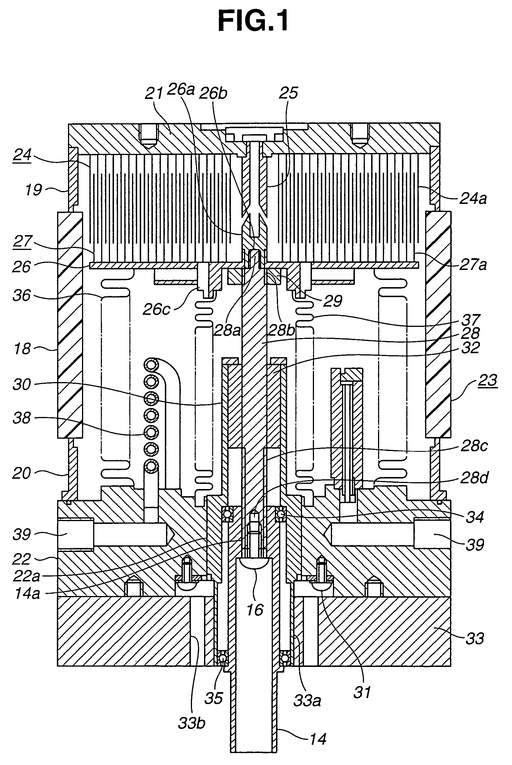
A vacuum variable capacitor includes an energization bellows arranged in a vacuum vessel and having ends mounted to a movable-electrode support plate and a movable side-end plate, respectively, a heat shielding bellows arranged inside the energization bellows and outside a slide-guide support and having ends mounted to the movable-electrode support plate and the movable side-end plate, respectively, and a cooling pipe interposed between the two bellows and for preventing transfer of heat generated in the energization bellows.

Description

BACKGROUND OF THE INVENTION[0001]The present invention relates to a vacuum variable capacitor for various circuits such as an oscillating circuit of a super power oscillator, an RF power circuit, and a tank circuit of an induction heating apparatus, and more particularly, to the vacuum variable capacitor with energization and heat shielding bellows.[0002]Vacuum capacitors are broadly divided into a vacuum fixed capacitor wherein a capacitance value is fixed and a vacuum variable capacitor wherein a capacitance value can be varied.[0003]The characteristics required of the vacuum variable capacitor are lower power loss, less heat generation during energization, longer life, etc. As will be described hereinafter in detail, the vacuum variable capacitor comprises an adjustment screw, the temperature of which becomes very high (up to about 300° C. by estimate) due to convection / radiation from the air side of a bellows as a heat generation source and heat conduction from the bellows, elec...

Claims


Application Information

Patent Timeline
Patent Type & Authority Patents(United States)
IPC IPC(8): H01G5/013H01G5/01H01G5/14
CPCH01G5/14
Inventor TAKAHASHI, EIICHIFUKAI, TOSHIMASAHAYASHI, NAOKI
Owner MEIDENSHA ELECTRIC MFG CO LTD
Learn More