
Variable capacitor

a variable capacitor and capacitor technology, applied in the field of variable capacitors, can solve the problems of increasing resistance, difficult to operate in a high frequency range, and the capacitance of the variable capacitor cannot be adjusted to an extremely small value or zero, so as to achieve the most efficient determination of maximum value and minimum value capacitance, high self-oscillation frequency, and high frequency range

Active Publication Date: 2005-12-13
MURATA MFG CO LTD
View PDF6 Cites 4 Cited by
  • Summary
  • Abstract
  • Description
  • Claims
  • Application Information

AI Technical Summary

Benefits of technology

[0009]In order to overcome the problems described above, preferred embodiments of the present invention provide a variable capacitor having a reduced resistance (ESR) and being adjustable to an extremely small overall capacitance.
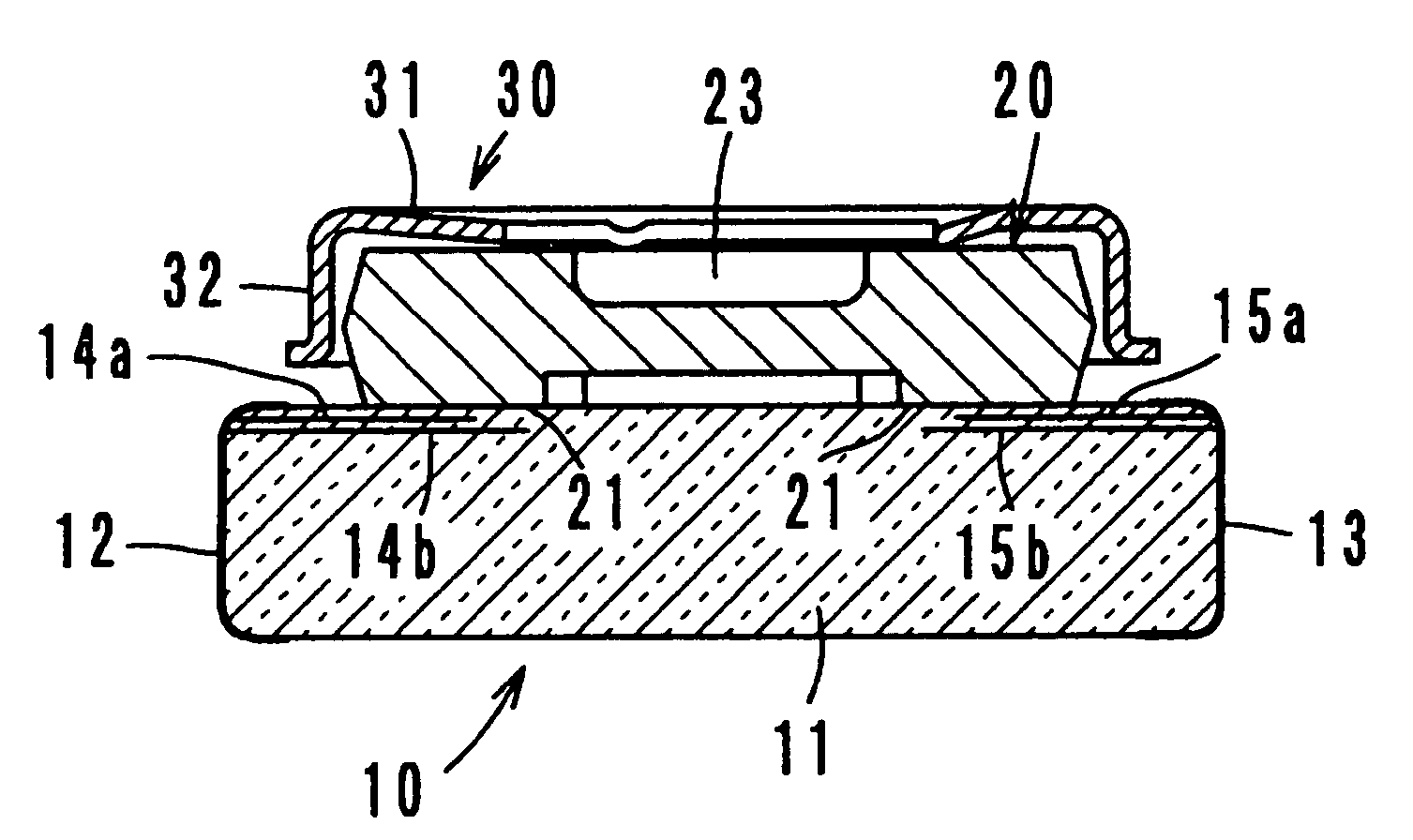
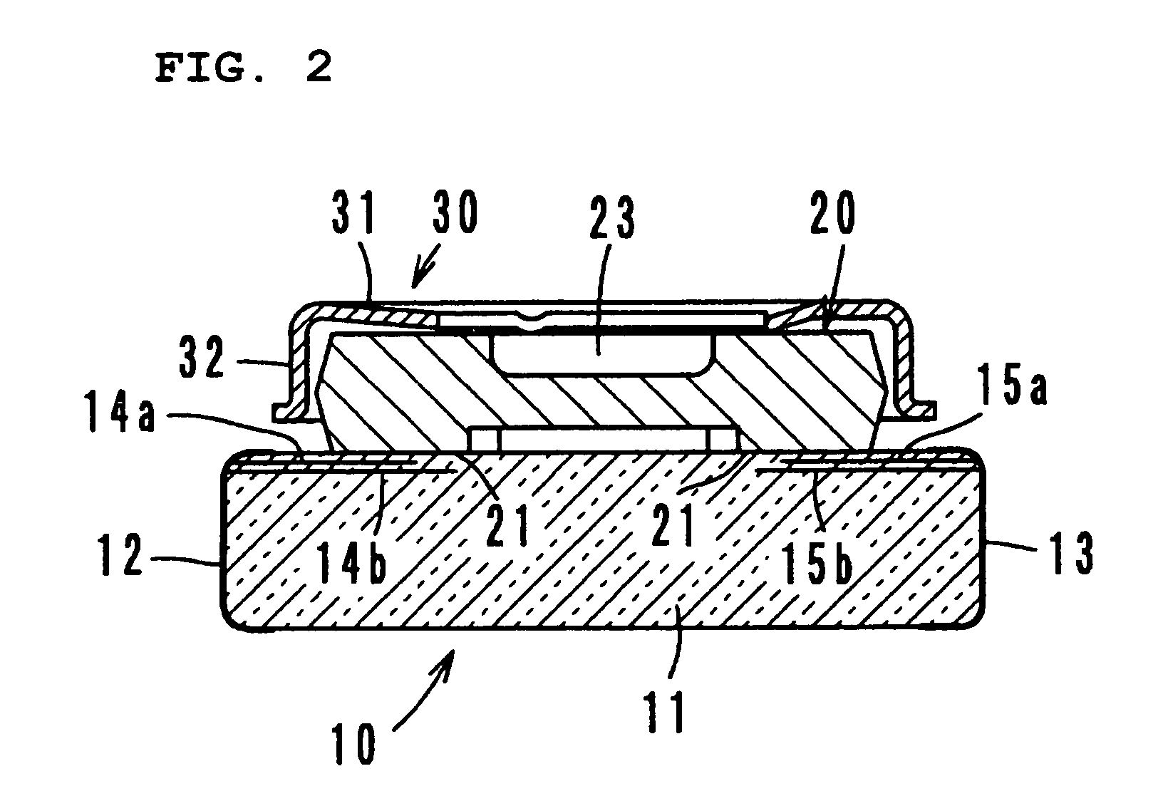
[0012]That is, since the first and the second stator electrodes are connected in parallel with each other, a resistance (ESR) resulting from a resistive component induced in the stator electrodes is reduced. In addition, each of the parallel-connected capacitors is variable so that the overall capacitance is adjustable to an extremely small value or zero. Accordingly, the variable capacitor has a high self-oscillation frequency and can operate in a high frequency range.
[0013]Preferably, in the variable capacitor, the rotor electrode passes through the positions where the area of overlap of the rotor electrode and the stator electrode alternately has a minimum value and a maximum value for every 90 degree rotation of the rotor. This design can determine the maximum value and the minimum value capacitances most efficiently.

Problems solved by technology

Unfortunately, in such a capacitor, the capacitances C11 and C12, which are connected in series, disadvantageously increase a resistance (ESR) resulting from a resistive component induced in the stator electrode.
As a result, the capacitance of the variable capacitor cannot be adjustable to an extremely small value or zero.
That is, the variable capacitor has a low self-oscillation frequency, thus making it difficult to operate in a high frequency range.

Method used


Image

  • Variable capacitor
  • Variable capacitor
  • Variable capacitor

Examples


second preferred embodiment (fig.6)

Second Preferred Embodiment (FIG. 6)

[0034]A variable capacitor according to a second preferred embodiment basically includes the same components as those in the first preferred embodiment. With reference to FIG. 6, the difference is that layers 14a, 14b, and 14c of a first stator electrode and layers 15a, 15b, and 15c of a second stator electrode are disposed in three layers of the dielectric substrate 11 of the stator 10. In FIG. 6, elements and blocks identical to those illustrated and described in relation to FIG. 3 are designated by like reference numerals, and duplicated descriptions are omitted.

[0035]The equivalent circuit of the second preferred embodiment is also shown in FIG. 7. In this preferred embodiment, capacitances C3 and C7 (not shown) are added. The effects are identical to those in the above-described first preferred embodiment of the present invention.

Other Preferred Embodiments

[0036]A variable capacitor according to the present invention is not limited to the abo...


PUM


Abstract

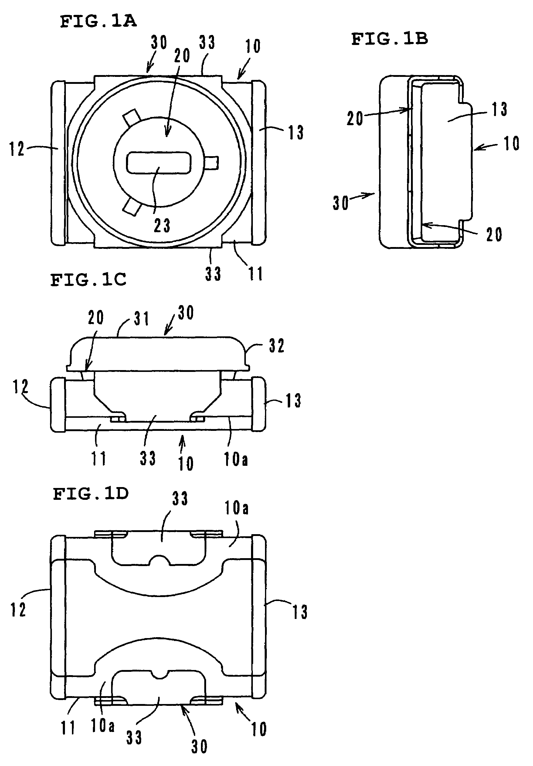
A variable capacitor includes a stator and a rotor rotatably supported by a cover relative to the stator. The stator includes a first stator electrode of two or more layers and a second stator electrode of two or more layers in the interior of a dielectric substrate. The first stator electrode is connected to a first external electrode and the second stator electrode is connected to a second external electrode. The rotor includes a rotor electrode of two pieces opposing the stator electrodes, and capacitances are defined in the areas of overlap of the rotor electrode and stator electrodes. The capacitances are adjustable to extremely small levels.

Description

BACKGROUND OF THE INVENTION[0001]1. Field of the Invention[0002]The present invention relates to a variable capacitor and, in particular, to a variable capacitor having a stator and a rotor that is rotatably supported relative to the stator, in which rotation of the rotor changes the area of overlap of a stator electrode and a rotor electrode so as to change the capacitance.[0003]2. Description of the Related Art[0004]Variable capacitors in which rotation of a rotor having a rotor electrode changes the area of overlap of a stator electrode in a stator and the rotor electrode to change their capacitance are disclosed in Japanese Unexamined Patent Application Publication No.10-233338 (hereinafter referred to as Patent Document 1) and U.S. Pat. No. 4,112,480 (hereinafter referred to as Patent Document 2).[0005]FIG. 8 shows the equivalent circuit of the variable capacitor disclosed in Patent Document 1. Rotation of a single rotor changes two capacitances C11 and C12. The variable capaci...

Claims


Application Information

Patent Timeline
Patent Type & Authority Patents(United States)
IPC IPC(8): H01G5/00H01G5/06
CPCH01G5/06
Inventor KATO, WATARU
Owner MURATA MFG CO LTD
Learn More