
Method and apparatus for determining a data rate in a high rate packet data wireless communications system

a wireless communication system and data rate technology, applied in the field of wireless data communication, can solve the problems of difficulty in voice and packet data services, and inability to achieve data transmission delay

Inactive Publication Date: 2005-12-06
QUALCOMM INC
View PDF11 Cites 69 Cited by
  • Summary
  • Abstract
  • Description
  • Claims
  • Application Information

AI Technical Summary

Benefits of technology

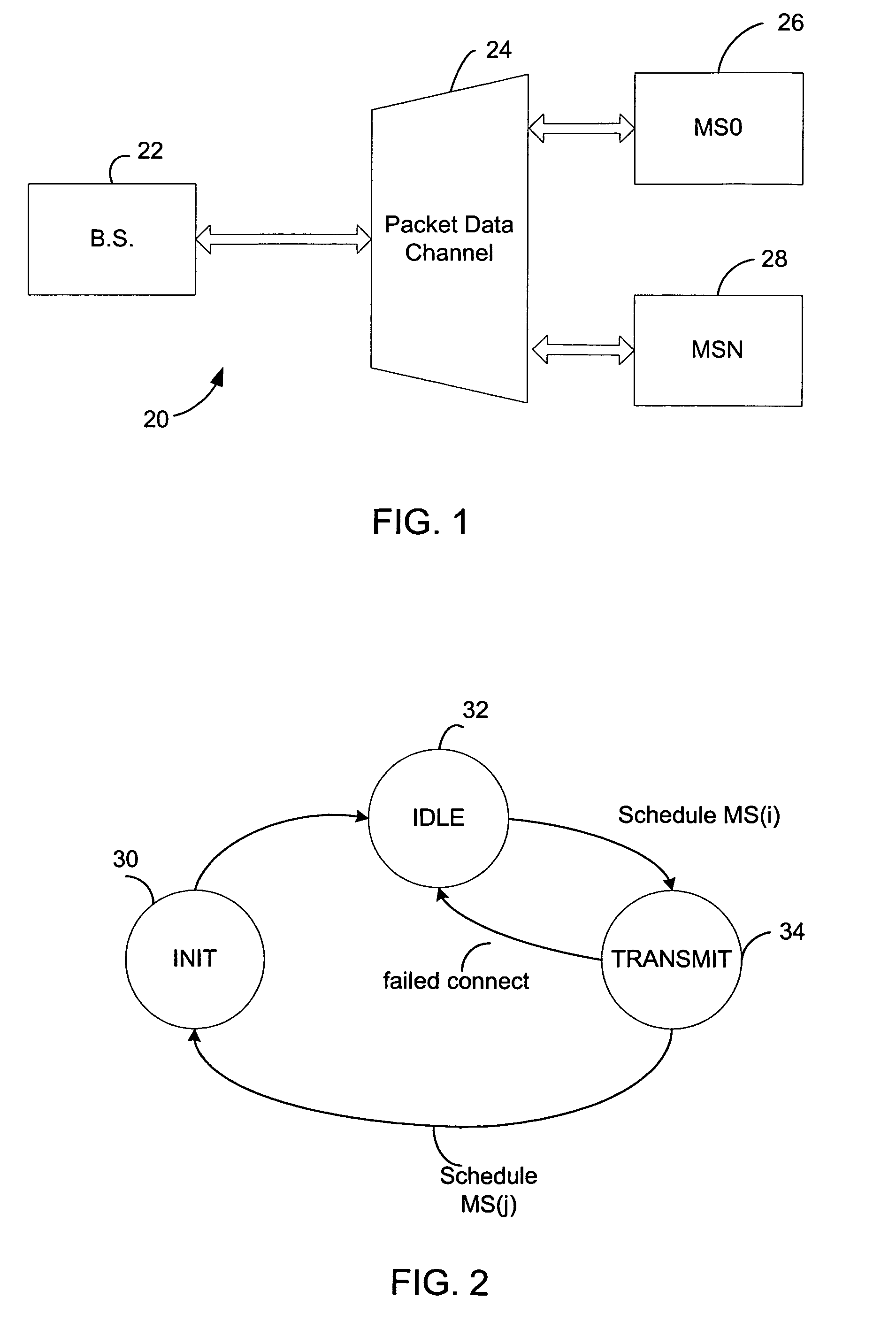
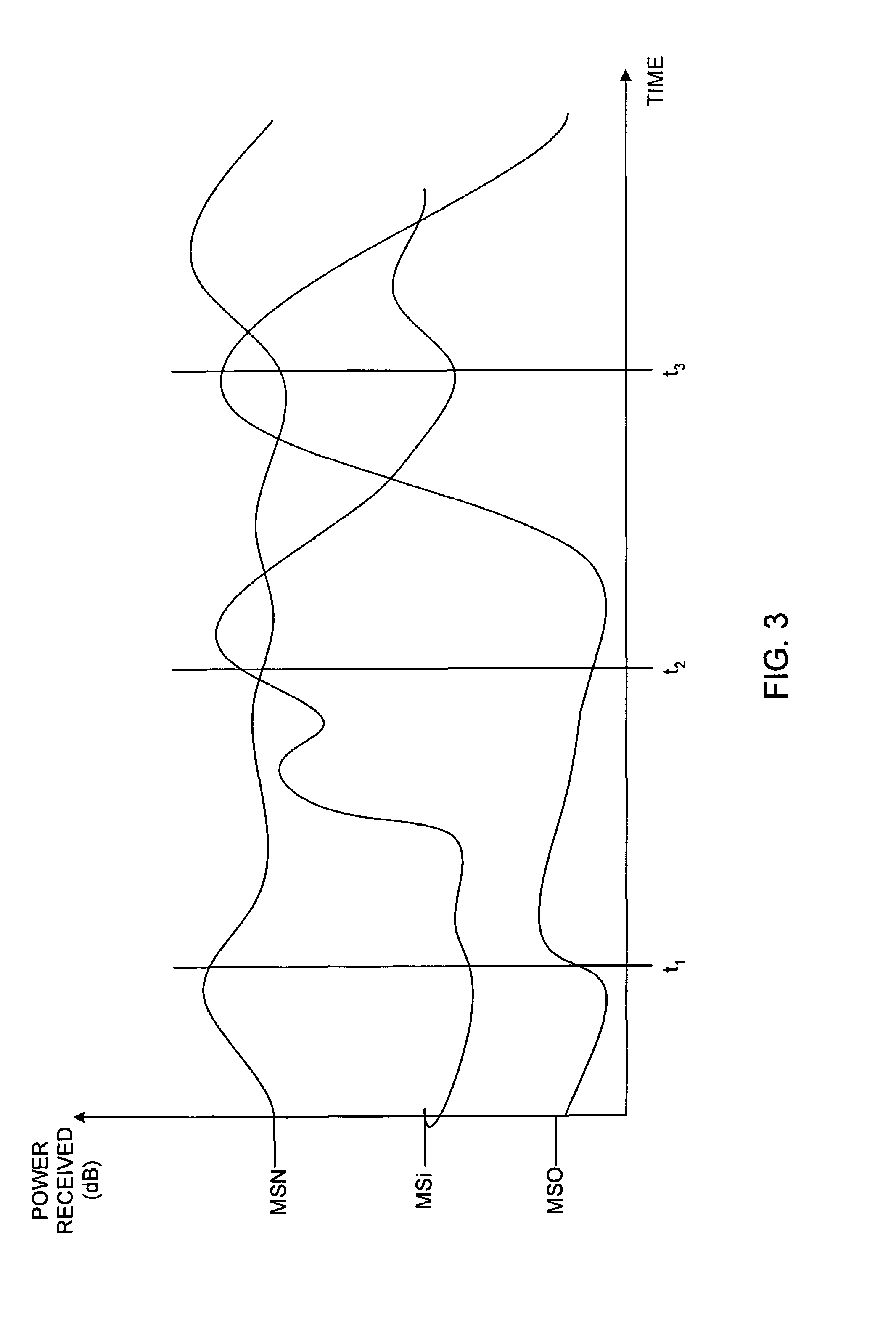
[0007]The disclosed embodiments provide a novel and improved method for high packet data rate and low delay data transmission in a wireless communication system. In one embodiment, a base station in a wireless communication system first sets up low delay data transmission, effectively as high priority, and then schedules packet data services according to the available traffic power after satisfying the low delay data. The packet data service transmits the packet data to one mobile user at a time. Alternate embodiments may provide packet data to multiple mobile users at a time, dividing the available power among the multiple users. At a given time, one user is selected as a target recipient based on the quality of the channel. The base station determines a ratio of the available power to the pilot channel power and provides the ratio to the selected mobile user. The ratio is referred to as the “Traffic-to-Pilot” ratio, or “T / P” ratio. The mobile user uses the ratio to calculate a data rate and sends that information back to the base station.

Problems solved by technology

A difficulty arises in applications requiring both voice and packet data services.
The circulation introduces delay into the transmission process.
Such delay is tolerable for data transmission, as the information is not used in real-time.
In contrast, the circulation delay is not acceptable for voice communications.

Method used


Image

  • Method and apparatus for determining a data rate in a high rate packet data wireless communications system
  • Method and apparatus for determining a data rate in a high rate packet data wireless communications system
  • Method and apparatus for determining a data rate in a high rate packet data wireless communications system

Examples


Embodiment Construction

[0025]While it is desirable to implement high rate packet data services and low delay, voice type services in one system, this is a difficult task due to the significant differences between voice services and data services. Specifically, voice services have stringent and predetermined delay requirements. Typically, the overall one-way delay of speech frames must be less than 100 msec. In contrast to voice, the data delay can become a variable parameter used to optimize the efficiency of the data communication system. As the condition of a channel to a given user will vary over time, and it is therefore possible to select the better times to transmit packets based on the channel condition.

[0026]Another difference between voice and data services involves the requirement of voice services for a fixed and common grade of service (GOS) for all users. For example, in a digital system the GOS requires a fixed and equal transmission rate for all users having no delay greater than a maximum ...


PUM


Abstract

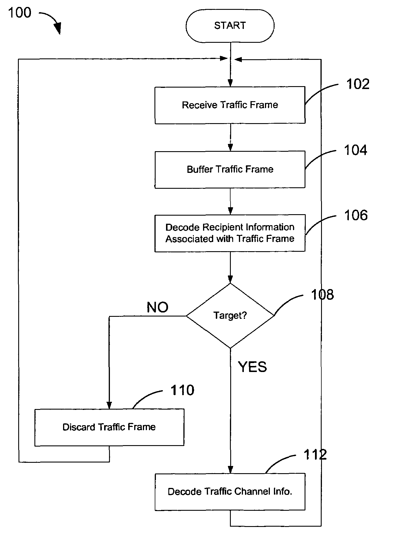
In a wireless communication system a method for combination transmission of packet data and low delay data. In one embodiment a parallel signaling channel provides a message to receivers indicating a target recipient of packet data. The message also identifies the transmission channels used for packet data transmissions. Each receiver may then selectively decode only packets where the message identifies the receiver as a target recipient. The data packets stored in a buffer are ignored if the target recipient is another mobile unit. In one embodiment, the message is sent concurrently with the data packet on a parallel channel. In one embodiment, the message is punctured into the high rate packet data transmission.

Description

REFERENCE TO RELATED CO-PENDING APPLICATIONS FOR PATENT[0001]The present invention relates to the following U.S. application for patent:[0002]U.S. patent application Ser. No. 08 / 963,386 entitled “METHOD AND APPARATUS FOR HIGH RATE PACKET DATA TRANSMISSION,” filed on Nov. 3, 1997, now U.S. Pat. No. 6,574,211, issued Jun. 3, 2003 to Padovani et al., and assigned to the assignee hereof which is hereby expressly incorporated by reference herein;[0003]U.S. patent application Ser. No. 09 / 697,375, filed Oct. 25, 2000, entitled METHOD AND APPARATUS FOR HIGH RATE PACKET DATA AND LOW DELAY DATA TRANSMISSIONS, and assigned to the assignee hereof.FIELD[0004]The present invention relates to wireless data communication. More particularly, the present invention relates to a novel and improved method and apparatus for high speed packet data and low delay data transmissions in a wireless communication system.BACKGROUND[0005]Increasing demand for wireless data transmission and the expansion of servic...

Claims


Application Information

Patent Timeline
IPC IPC(8): H04B7/005H04B7/26H04L12/56H04W28/22H04W52/16H04W52/26H04W52/28H04W52/32H04W52/34
CPCH04L1/0002H04W28/22H04W52/16H04W52/286H04W52/346H04L1/0026H04W52/267H04W52/325H04L1/001
Inventor LUNDBY, STEIN A.RAZOUMOV, LEONIDBAO, GANGWEI, YONGBIN
Owner QUALCOMM INC
Learn More