
Tactile warning surfaces for walkways and method

Inactive Publication Date: 2005-12-06
SCHABACKER NOLAN D
View PDF19 Cites 51 Cited by
  • Summary
  • Abstract
  • Description
  • Claims
  • Application Information

AI Technical Summary

Benefits of technology

[0008]The method for forming tactile warning surfaces of the subject invention, solves the problems associated with making, transporting, and installing pre-formed tactile warning panels and the problems associated with the on site molding of tactile warning surfaces discussed above. The method for forming tactile warning surfaces of the subject invention can be applied with equal ease when providing new concrete slabs of walkways with tactile warning surfaces or retrofitting existing concrete slabs of walkways with tactile warning surfaces.
[0010]Preferably, the pins used in the tactile warning surface structure of the subject invention are made of a material, such as but not limited to a cementitious material, that has the same or substantially the same coefficient of thermal expansion as the concrete slab. By having the coefficient of thermal expansion of the pins and the concrete slab the same or substantially the same, the formation of cracks in the slab due to a relatively greater thermal expansion of the pins is avoided. Since a pin mad of a cementitious material will have the same or substantially the same coefficient of thermal expansion as the concrete slab and can be made to have a compressive strength equal to or greater than the compressive strength of the concrete slab, a preferred material for the pins is a cementitious material. As used in this specification and claims, the term “cementitious material” means a powder of alumina, silica, lime, iron oxide, and magnesium oxide burned together in a kiln that is finely pulverized (e.g. portland cement) and combined with water; mortar (a powder of alumina, silica, lime, iron oxide, and magnesium oxide burned together in a kiln and finely pulverized, such as portland cement, that is combined with sand and water); and / or concrete (a powder of alumina, silica, lime, iron oxide, and magnesium oxide burned together in a kiln and finely pulverized, such as portland cement, that is combined with a mineral aggregate, such as sand and gravel, and water). Preferably, the color of the upper end head portions of the pins contrasts with the color of the concrete slab to make the tactile warning surface easier to see.

Problems solved by technology

However, there are problems associated with the installation of these pre-formed tactile warning panels in both new and existing concrete slab installations.
The above procedures require the recessed surface that receives the pre-formed tactile warning panel(s) to be formed while the concrete is still soft, are time consuming, and may require at least one panel to be cut at the job site so that the tactile warning panels cover a prescribed area.
It can be even more time consuming and difficult to ensure that the upper surfaces of the tactile warning panels are laying in the same plane as each other and the surface of the surrounding concrete slab so that no lip on which a person might trip is created between the panels and / or the panels and the surface of the surrounding concrete slab.
This problem is especially acute when unskilled labor is used to install the tactile warning panels.
Again the installation procedures are time consuming and may require at least one panel to be cut at the job site so that the tactile warning panels cover a prescribed area.
In addition, if the molding of the truncated domes in the surface of the newly formed concrete slab is not performed while the concrete is at the proper consistency or if the molding operation is otherwise defective, the new concrete slab with its defective tactile warning surface may have to be removed and whole procedure may have to be repeated.

Method used


Image

  • Tactile warning surfaces for walkways and method
  • Tactile warning surfaces for walkways and method
  • Tactile warning surfaces for walkways and method

Examples


Embodiment Construction

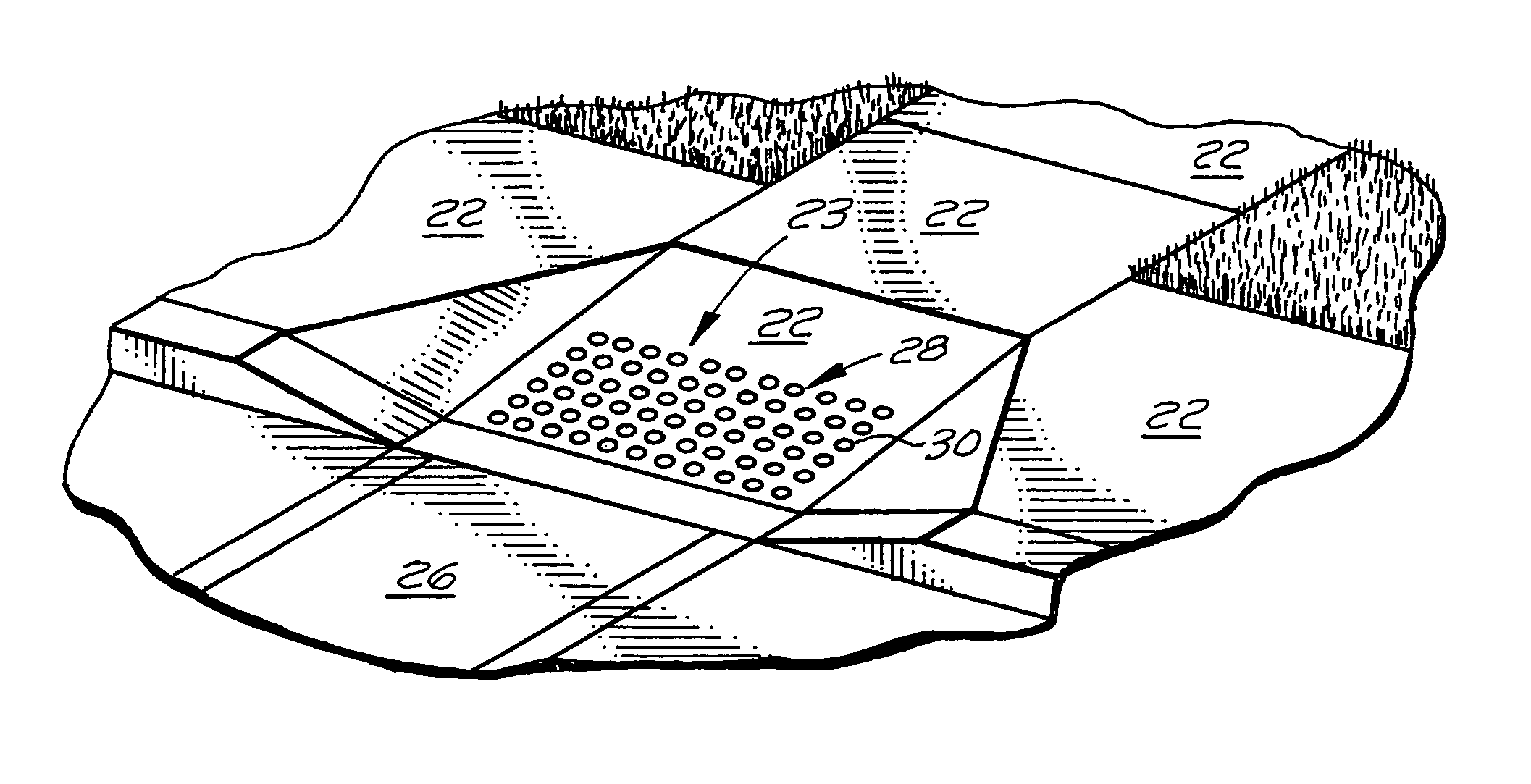
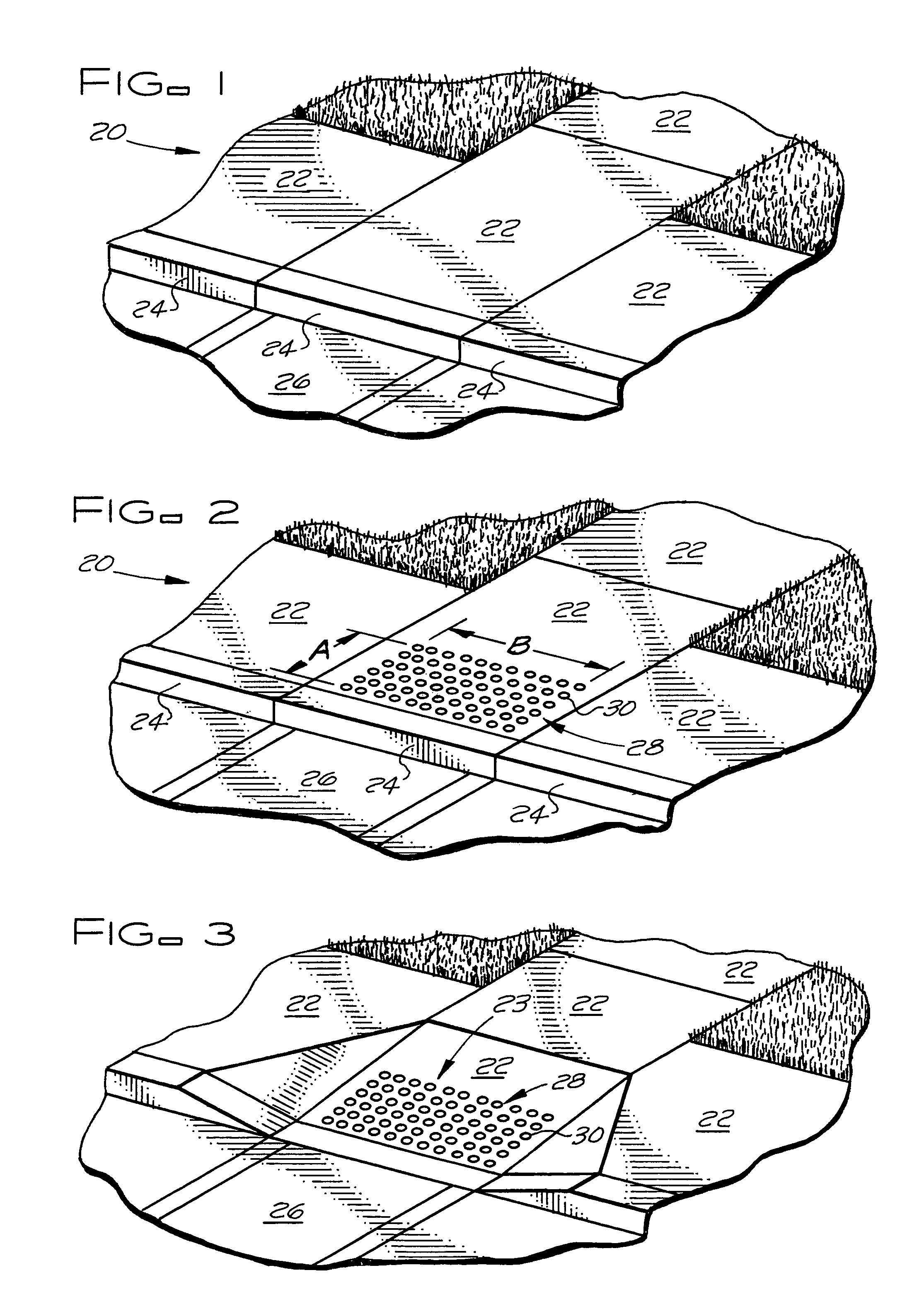
[0023]FIG. 1 is an example of a walkway made of concrete slabs for which the method of the subject invention can be used to make a tactile warning surface structure of the subject invention. In the example shown, the walkway is a sidewalk 20 of concrete slabs 22 and a curbing 24. The sidewalk 20 is located adjacent a potentially hazardous area for people who are visually impaired or blind, in this case a pedestrian crosswalk 26 crossing a street, to warn them that they are approaching a hazardous area. The sidewalk 20 can be a newly constructed sidewalk, provided the concrete of the slabs 22 has sufficiently set and cured to permit drilling, or the sidewalk can be an existing sidewalk being retrofitted with a tactile warning surface.

[0024]FIG. 2 shows the sidewalk 20 of FIG. 1 with a tactile warning surface structure 28 of the subject invention installed in a concrete slab 22 of the sidewalk that is located adjacent the crosswalk 26. The tactile warning surface structure 28 is forme...


PUM


Abstract

A tactile warning surface structure having underfoot detectability is formed in place by a method wherein the shank portions of a plurality pins are inserted into and bonded to a plurality of holes formed in an upper surface of a concrete slab of a walkway. The holes are located within a defined area of the upper surface of the concrete slab and are spaced from each other in a predetermined pattern so that, when the shank portions of the pins are inserted into and bonded to the holes in the concrete slab with the upper end head portions of the pins projecting upward beyond the upper surface of the concrete slab at least a minimum distance, the pins in the defined area of the upper surface of the concrete slab form a tactile warning surface having underfoot detectability.

Description

BACKGROUND OF THE INVENTION[0001]The subject invention relates to tactile warning surfaces with underfoot detectability that are included in walkways for alerting the handicapped (e.g. the blind or visually impaired) and other persons that they are entering potentially hazardous areas and for safely guiding persons through the potentially hazardous areas. The subject invention also relates to an in-place method for making tactile warning surfaces in walkways at a job site. Tactile warning surfaces are used for both outdoor and indoor walkway applications (exterior and interior walkway applications) in connection with walkways formed by concrete slabs that are associated with potentially hazardous areas. For example, tactile warning surfaces are used with concrete slab walkways such as but not limited to: sidewalks; curb ramps; wheelchair ramps, pedestrian crossings; road pavement; parking lot and garage pavement; platforms of train, bus and other transit stations; platforms of stadi...

Claims


Application Information

Patent Timeline
IPC IPC(8): A61H3/06E01C11/22E01C11/24E01C23/09
CPCA61H3/066E01C11/222E01C23/0993
Inventor SCHABACKER, NOLAN D.
Owner SCHABACKER NOLAN D
Learn More