Illumination device and liquid crystal display device

a technology of liquid crystal display and illumination device, which is applied in the direction of lighting and heating apparatus, mechanical apparatus, instruments, etc., can solve the problems of significant increase in the weight of illumination device, and achieve the effect of easy thinning, high brightness and ligh

Inactive Publication Date: 2005-12-06
ALPS ALPINE CO LTD
View PDF10 Cites 13 Cited by
  • Summary
  • Abstract
  • Description
  • Claims
  • Application Information

AI Technical Summary

Benefits of technology

[0032]According to the above structure, it is possible to provide an illumination device capable of making uniform the distribution of the amount of emitted light to a direction, to which the light guider is extended and of obtaining uniform illumination light in a surface of the planar illuminator.
[0033]In the liquid crystal device according to the present invention, the illumination device according to the claims is disposed in the rear side of the liquid crystal panel. According to the above structure, it is possible to provide a thin and light liquid crystal display device capable of displaying images with high brightness by including the illumination device according to the present invention capable of being easily made thin and light.

Problems solved by technology

In particular, when the illumination device is enlarged, significant increase in the weight of the illumination device is caused.

Method used


Image

  • Illumination device and liquid crystal display device
  • Illumination device and liquid crystal display device
  • Illumination device and liquid crystal display device

Examples


Embodiment Construction

[0049]An embodiment of the present invention will now be described with reference to drawings.

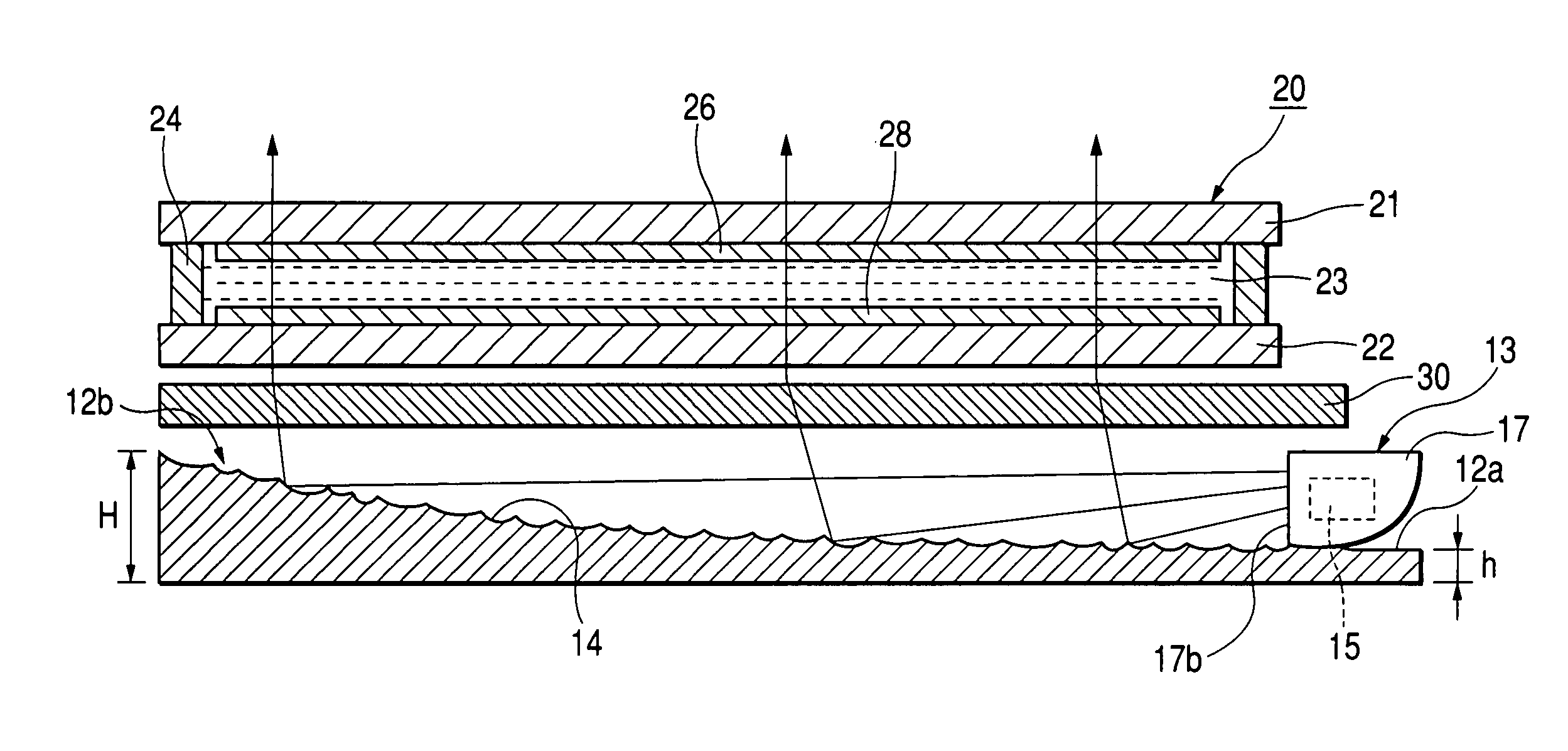
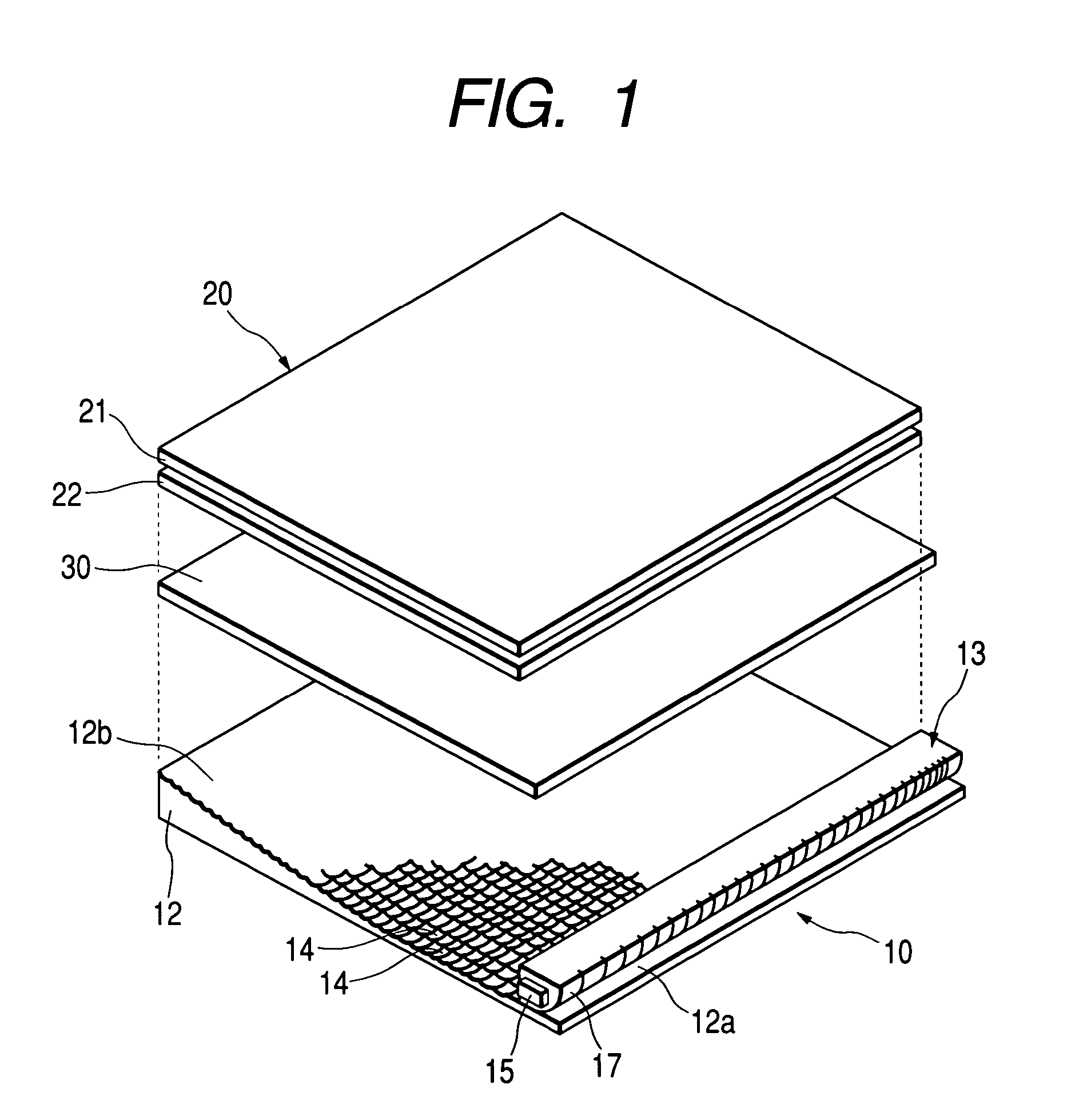
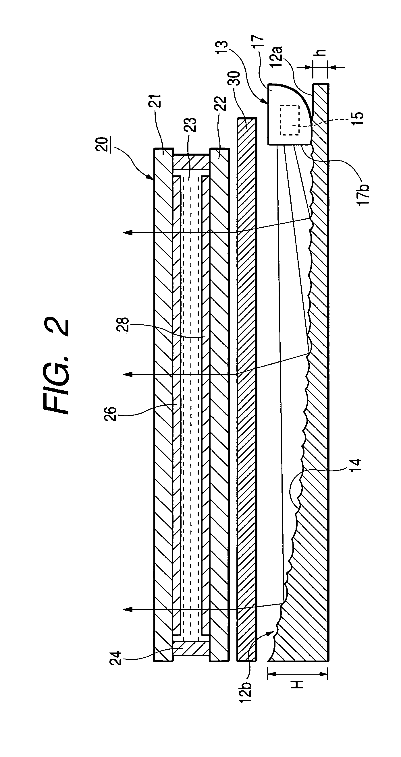
[0050]FIG. 1 is a perspective view of a liquid crystal display device according to an embodiment of the present invention. FIG. 2 is a sectional view of the liquid crystal display device illustrated in FIG. 1. The liquid crystal display device according to the embodiment, as illustrated in FIGS. 1 and 2, includes a liquid crystal panel 20 and a backlight (an illumination device) 10 arranged on the rear side of (below the liquid crystal panel in Figure) the liquid crystal panel 20. In the liquid crystal display device according to the present embodiment, optical means 30 having a light diffusing function or a directivity controlling function is arranged between the liquid crystal panel 20 and the backlight 10.

[0051]The backlight 10 includes a planar illuminator 12 having a reflection surface 12b formed at its upper surface, and a light source portion (a light source) 13 arranged on a light s...


PUM

PropertyMeasurementUnit
vertical angleaaaaaaaaaa
distanceaaaaaaaaaa

Abstract

An illumination device includes a light source and a planar illuminator for emitting light of the light source portion from one surface thereby to illuminate a liquid crystal panel. The planar illuminator has a reflection surface, on which minute concavo-convex shapes are substantially randomly formed. Surface emission is performed by diffuse reflecting the light irradiated from the light source portion by the reflection surface.

Description

[0001]This application claims the benefit of priority to Japanese Patent Application 2002-334994, filed on Nov. 19, 2002.BACKGROUND OF THE INVENTION[0002]1. Field of the Invention[0003]The present invention relates to an illumination device and a liquid crystal display device.[0004]2. Description of the Related Art[0005]Illumination device such as a frontlight and a backlight used for liquid crystal display device basically include a light guide plate and a light source disposed on the side section of the light guide plate. Light incident from the side sections of the light guide plates is reflected by a prism formed on the opposite sides to the emission surfaces of the light guide plates and is emitted from the emission surfaces. As a result, the illumination devices illuminate illuminated objects such as liquid crystal panels. It is suggested that the traveling direction of the light incident on the liquid crystal panels be controlled and that display brightness be improved by dis...

Claims


Application Information

Patent Timeline
Patent Type & Authority Patents(United States)
IPC IPC(8): G02F1/13357F21S2/00F21V7/04F21V8/00F21Y101/02G02B6/00
CPCG02B6/0038G02F1/133605G02F1/133615G02B6/0053G02B6/0061
Inventor NAGAKUBO, HIDEAKISATO, NORIKAZU
Owner ALPS ALPINE CO LTD
Why Eureka
Try Eureka