
Fuel injection system for internal combustion engines with gasoline direct injection, which includes optional injection into the intake tube, and method for operating it

a fuel injection system and internal combustion engine technology, applied in the direction of electrical control, process and machine control, etc., can solve the problems of affecting the operation of the fuel injection system. , to achieve the effect of improving the dissolving of possible deposits, prolonging the holding time of fuel, and increasing fuel consumption

Inactive Publication Date: 2005-12-06
ROBERT BOSCH GMBH
View PDF10 Cites 10 Cited by
  • Summary
  • Abstract
  • Description
  • Claims
  • Application Information

AI Technical Summary

Benefits of technology

[0008]It has turned out that intermittently injecting fuel into the intake tube by means of the second injection valve can prevent deposits from forming. In addition, possibly existing deposits can be broken down. These effects are based on the fact that the fuel injected by means of the second injection valve takes the form of a fine fuel mist in the intake tube and the additives contained in the fuel prevent the formation of deposits by wetting the appropriate surfaces of the intake tube and e.g. the inlet valves. In addition, this fine fuel mist dissolves possibly existing deposits from the intake tube and / or the inlet valves, thus also permitting the effective elimination of possibly existing deposits.
[0009]If needed, a second injection valve can also be provided for each cylinder of the internal combustion engine. As a result, the fuel can be injected into the intake tube in the immediate vicinity of the inlet valves, which even more effectively suppresses the formation of deposits. This measure also intensifies the breaking down of existing deposits.
[0014]Another embodiment of the method according to the invention can include the provision that during the warm-up phase of the engine, the second injection valve injects fuel into the intake tube so that in particular, the formation of deposits in the intake tube and on the inlet valves is prevented and so that an additional fuel quantity possibly required for the starting process is injected. As a result, the injection of fuel by the second injection valve does not cause an increase in fuel consumption.
[0015]Alternatively, it is also possible when shutting off the engine to inject fuel into the intake tube by means of the injection valve in order to achieve a long holding time of the fuel, both in the intake tube and against the injection valves, and consequently to improve the dissolving of possibly existing deposits.

Problems solved by technology

Internal combustion engines with exhaust recirculation and gasoline direct injection (GDI) have the problem of deposits building up in the intake tube and on the inlet valves.
At the beginning, these deposits are still soft and sticky, but change over the course of time into hard deposits and can lead to the jamming or destruction of moving parts.
In the intake section, these deposits pose a threat chiefly to the inlet valves and their valve guides.
In addition, the presence of these deposits leads to a reduction of the free flow cross section in the intake tube, which adversely affects the operating behavior and the power output of the engine.

Method used


Image

  • Fuel injection system for internal combustion engines with gasoline direct injection, which includes optional injection into the intake tube, and method for operating it
  • Fuel injection system for internal combustion engines with gasoline direct injection, which includes optional injection into the intake tube, and method for operating it

Examples


Embodiment Construction

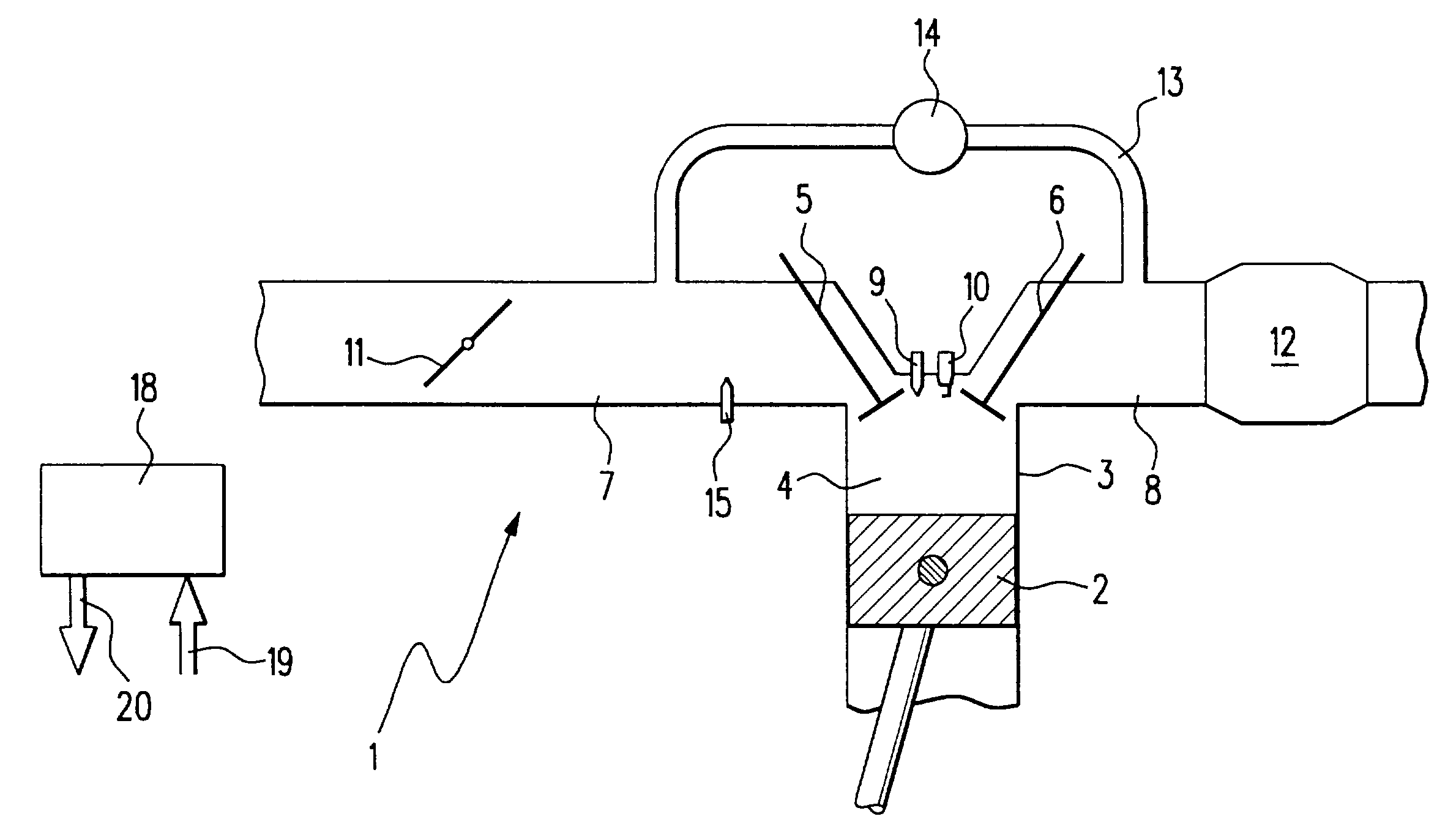
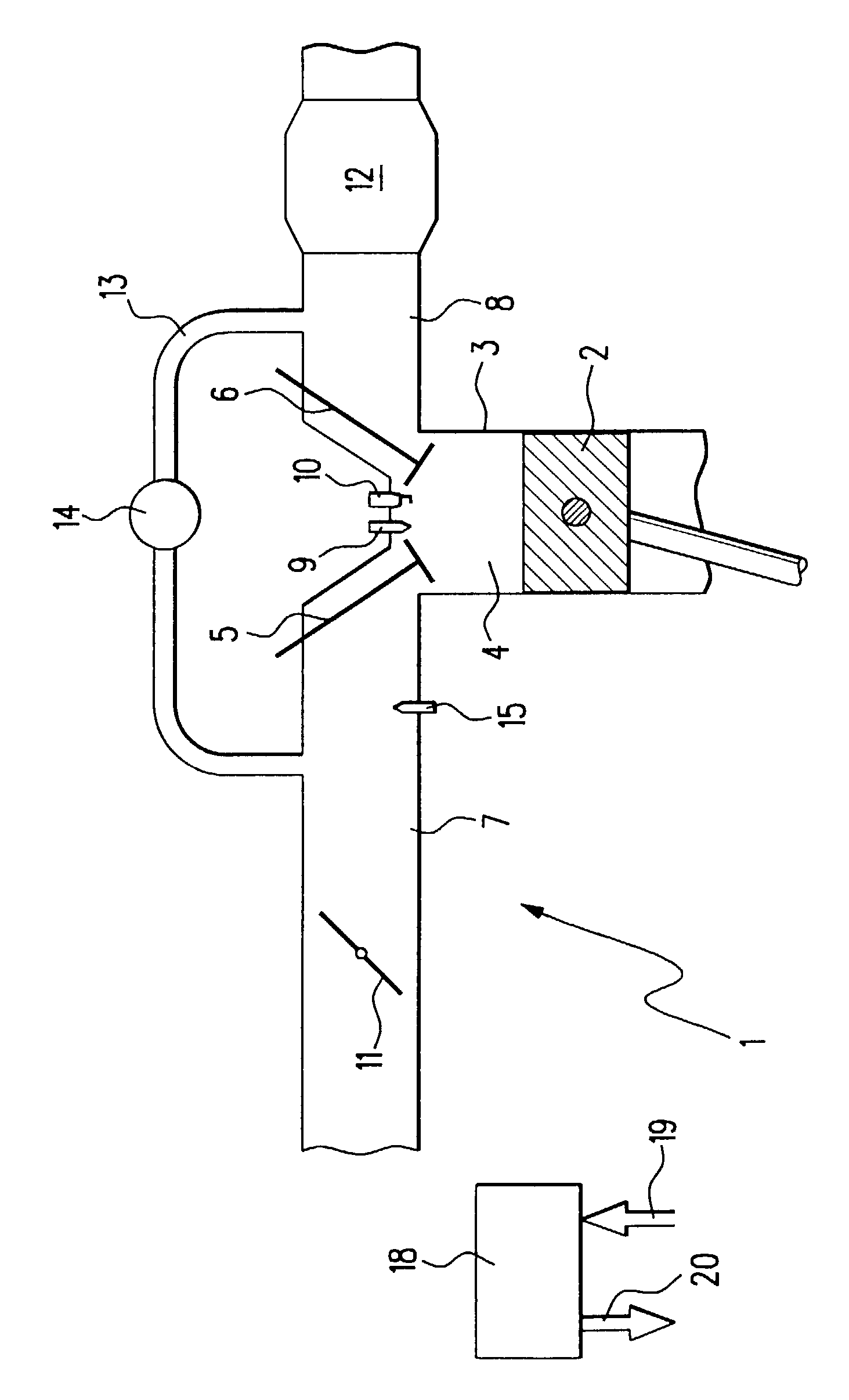
[0018]The FIGURE schematically depicts an internal combustion engine 1 of a motor vehicle with gasoline direct injection in which a piston 2 oscillates in a cylinder 3. The cylinder 3 is provided with a combustion chamber 4, which is defined among other things by the piston 2, an inlet valve 5, and an outlet valve 6. An intake tube 7 is provided upstream of the inlet valve 5. The outlet valve 6 is adjoined by an exhaust pipe 8. Naturally, the engine may have a number of cylinders, and several inlet valves 5 and several outlet valves 6 can be provided per cylinder 3.

[0019]In the vicinity of the inlet valve 5 and the outlet valve 6, a first injection valve 9 and a spark plug 10 protrude into the combustion chamber 4; fuel can be injected directly into the combustion chamber 4 by means of the first injection valve 9. The spark plug 10 can ignite the fuel in the combustion chamber 4. This type of operation is referred to as gasoline direct injection (GDI).

[0020]The intake tube 7 contain...


PUM


Abstract

A fuel injection system for GDI internal combustion engines, which has a second injection valve in the intake tube, and a method for operating this fuel injection system. By injecting fuel into the intake tube at intervals by means of the second injection valve, the formation of deposits in the intake tube and on the inlet valve, which are produced due to the recirculation of exhaust gas through the exhaust recirculation tube, can be prevented and possibly existing deposits can be broken down.

Description

BACKGROUND OF THE INVENTION[0001]1. Field of the Invention[0002]The current invention relates to a fuel injection system for internal combustion engines with gasoline direct injection, which has a high-pressure fuel pump, a control unit, and a first injection valve for each cylinder of the engine.[0003]2. Brief Description of the Prior Art[0004]Internal combustion engines with exhaust recirculation and gasoline direct injection (GDI) have the problem of deposits building up in the intake tube and on the inlet valves. These deposits are caused by the amount of soot and partially polymerized hydrocarbons contained in the recirculated exhaust. At the beginning, these deposits are still soft and sticky, but change over the course of time into hard deposits and can lead to the jamming or destruction of moving parts. In the intake section, these deposits pose a threat chiefly to the inlet valves and their valve guides.[0005]In addition, the presence of these deposits leads to a reduction ...

Claims


Application Information

Patent Timeline
IPC IPC(8): F02B23/08F02B23/10F02B75/12F02D17/00F02D41/00F02D41/04F02D41/06F02D41/08F02D41/34F02M26/50F02M61/14F02M63/00F02M69/00F02M69/04
CPCF02B23/101F02D41/068F02D41/3094F02M25/0701F02B23/08F02B2075/125F02D41/0065F02D41/042F02D2041/389F02D2200/0406F02M25/0715Y02T10/125Y02T10/123F02M26/50F02M26/13Y02T10/12
Inventor PILGRAM, GUIDOMAIER, MARTIN
Owner ROBERT BOSCH GMBH
Learn More