
Assembly of modules with magnetic anchorage for the construction of stable grid structures

a technology of modular modules and grid structures, applied in the field of modular modules, can solve the problems of excessive increase in the weight and cost of the same grid structure, and the shape of the grid structure does not have the appropriate stability and self-support capability, so as to improve the resistance to deformation and increase the weight or total cost

Inactive Publication Date: 2005-11-29
VICENTELLI CLAUDIO
View PDF17 Cites 97 Cited by
  • Summary
  • Abstract
  • Description
  • Claims
  • Application Information

AI Technical Summary

Benefits of technology

[0007]The main object of the present invention is to provide an assembly of modules with magnetic anchorage for the construction of grid structures that, through the use of a same number of magnetic modules, achieve an improved resistance to the deformation caused by shearing, slipping, bending or torsion stresses. Another object of the present invention is to provide an assembly of modules with magnetic anchorage for the construction of grid structures which makes any required grid structure stable without it being necessary to modify its shape and excessively increase its weight or total cost.
[0009]The panels can be made in a lightweight and economical material and enable extremely stable grid structures to be obtained, while maintaining the original simplicity and flexibility of assembly of the modules.
[0010]The panels for stabilisation of the grid structure can also allow new ways of using grid structures both as elements strictly for amusement and as display or furnishing elements.

Problems solved by technology

In all systems of assembly with magnetic anchorage known today, and above all in those assemblies with magnetic anchorage which under-exploit the magnetic energy available for anchorage between modules, some shapes of the grid structure do not have the appropriate stability and self-support capability, particularly with reference to resistance to shearing or slipping and to bending stress.
This solution, in addition to modifying the original shape of the required grid structure, can cause excessive increase in the weight and cost of the same grid structure.

Method used


Image

  • Assembly of modules with magnetic anchorage for the construction of stable grid structures
  • Assembly of modules with magnetic anchorage for the construction of stable grid structures

Examples


Embodiment Construction

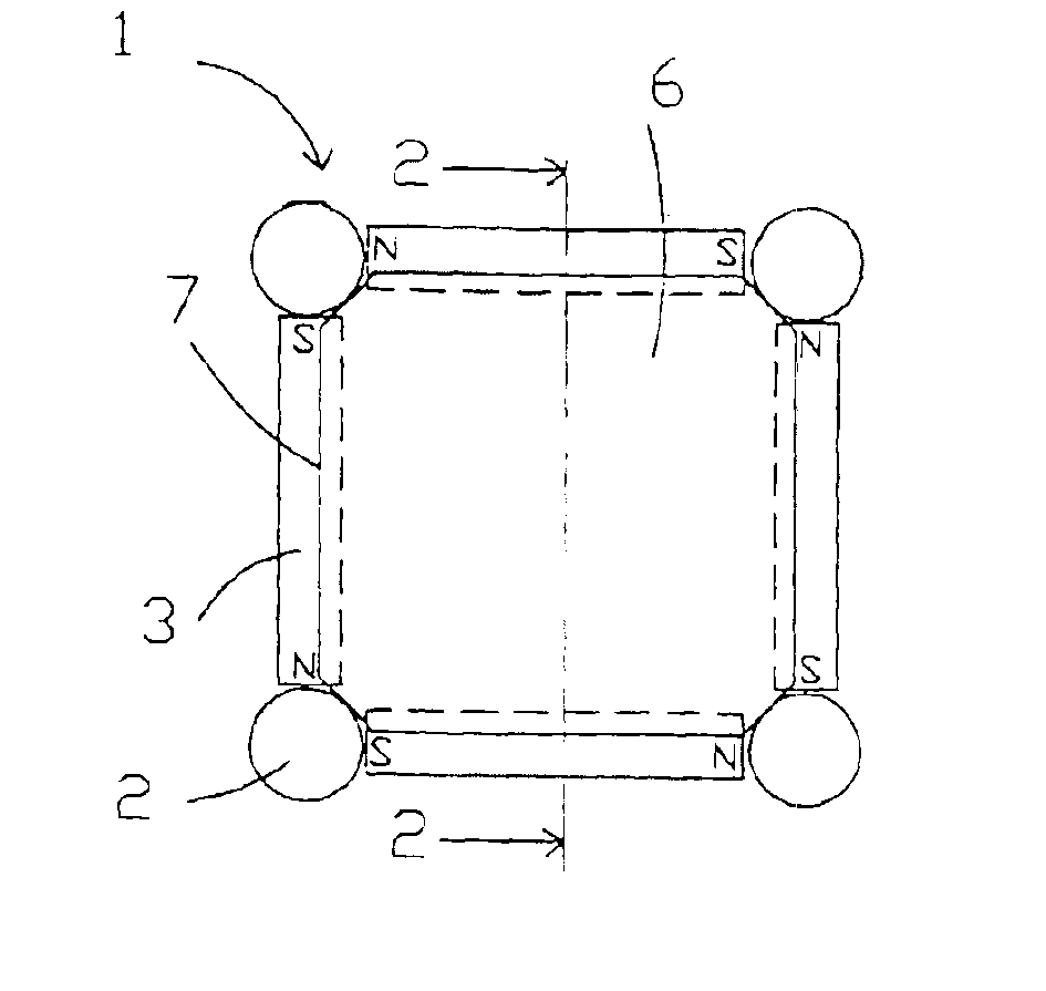
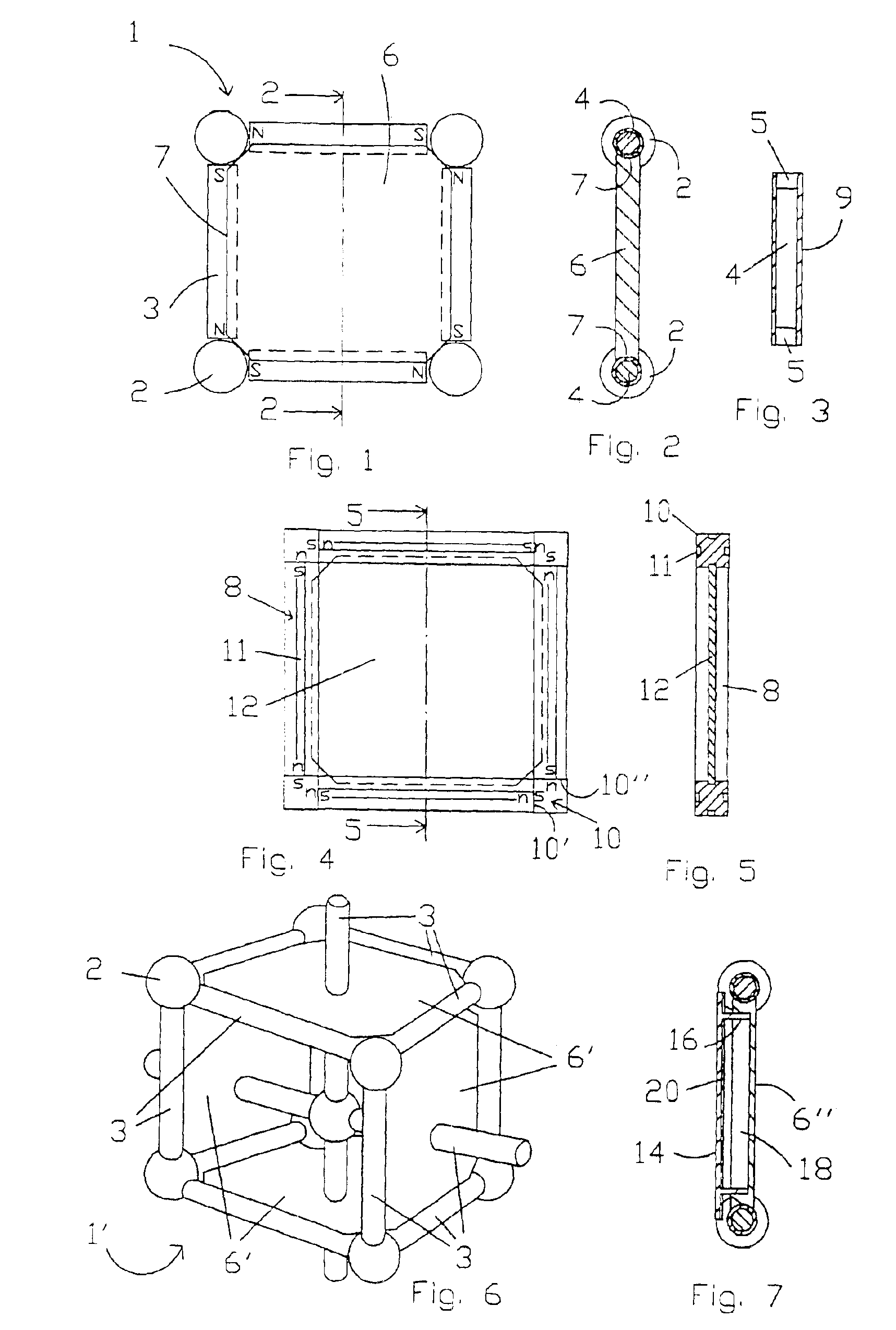
[0020]With reference to FIGS. 1, 2 and 3, a two-dimensional assembly 1 of eight modules comprising four spherical modules 2 and four cylindrical modules 3 is illustrated.

[0021]The spherical modules 2 consist of a ferromagnetic ball member for example of steel, while the cylindrical modules 3 each comprises a central ferromagnetic cylindrical yoke 4 to each of whose opposite ends a corresponding cylindrical element 5 of permanently magnetic material is provided.

[0022]The permanently magnetic elements 5 are magnetized axially and are arranged with the ends of opposite magnetic polarity in such a way as to be connected in series via the ferromagnetic yoke 4.

[0023]If necessary the structure of the cylindrical modules 3 can be contained in a non-magnetic covering matrix 9.

[0024]The assembly 1 comprises a square plaque or panel 6 with cut-away corners which defines, in the direction of the thickness of the panel 6, lateral recessed edges 7 with an arched cross profile.

[0025]The radius of ...


PUM

PropertyMeasurementUnit
Transparencyaaaaaaaaaa
Magnetismaaaaaaaaaa
Ferromagnetismaaaaaaaaaa

Abstract

In an assembly of modules with magnetic anchorage for the construction of grid structures, one or more elements for stabilization of the grid structure are inserted in the form of panels (6, 12, 6″) which can be removably slotted in corresponding polygonal areas circumscribed by the modules of the grid structure.

Description

BACKGROUND OF THE INVENTION[0001]The present invention relates to an assembly of modules that uses magnetic anchorage for the construction of a stable grid structure.[0002]From the Italian patent no. 01301090, owned by the same Applicant, an assembly of modules is known which optimizes the exploitation of magnetic energy available for the anchorage of the modules in such a way as to achieve a plurality of grid structures having the most complex and inventive shapes.[0003]The point of magnetic coupling between two modules can be chosen as required at any one of the zones of the magnetically active surface and / or ferromagnetic surface of one of the modules and is not limited by a predefined orientation between the two modules in such a way that the modules of the assembly can be combined overall one with the other, obtaining a plurality of shapes.[0004]In all systems of assembly with magnetic anchorage known today, and above all in those assemblies with magnetic anchorage which under-...

Claims


Application Information

Patent Timeline
IPC IPC(8): A47B47/03A47B47/04A63H33/10A63F9/00A63F9/10A63F9/34A63H33/04A63H33/26G09B1/38G09F7/04G09F15/00
CPCA63F9/34A63H33/046G09F7/04A63F9/1044
Inventor VICENTELLI, CLAUDIO
Owner VICENTELLI CLAUDIO
Learn More