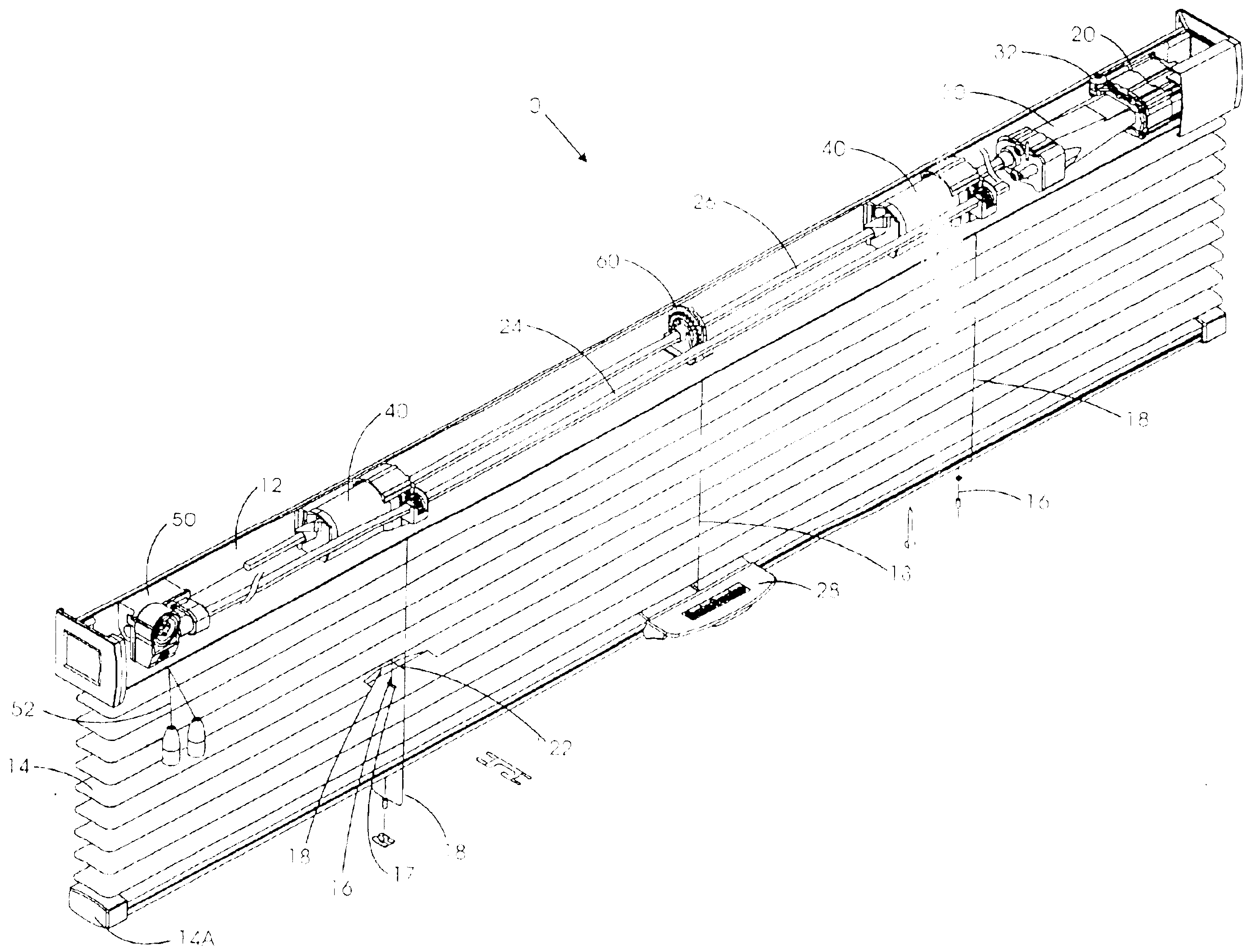
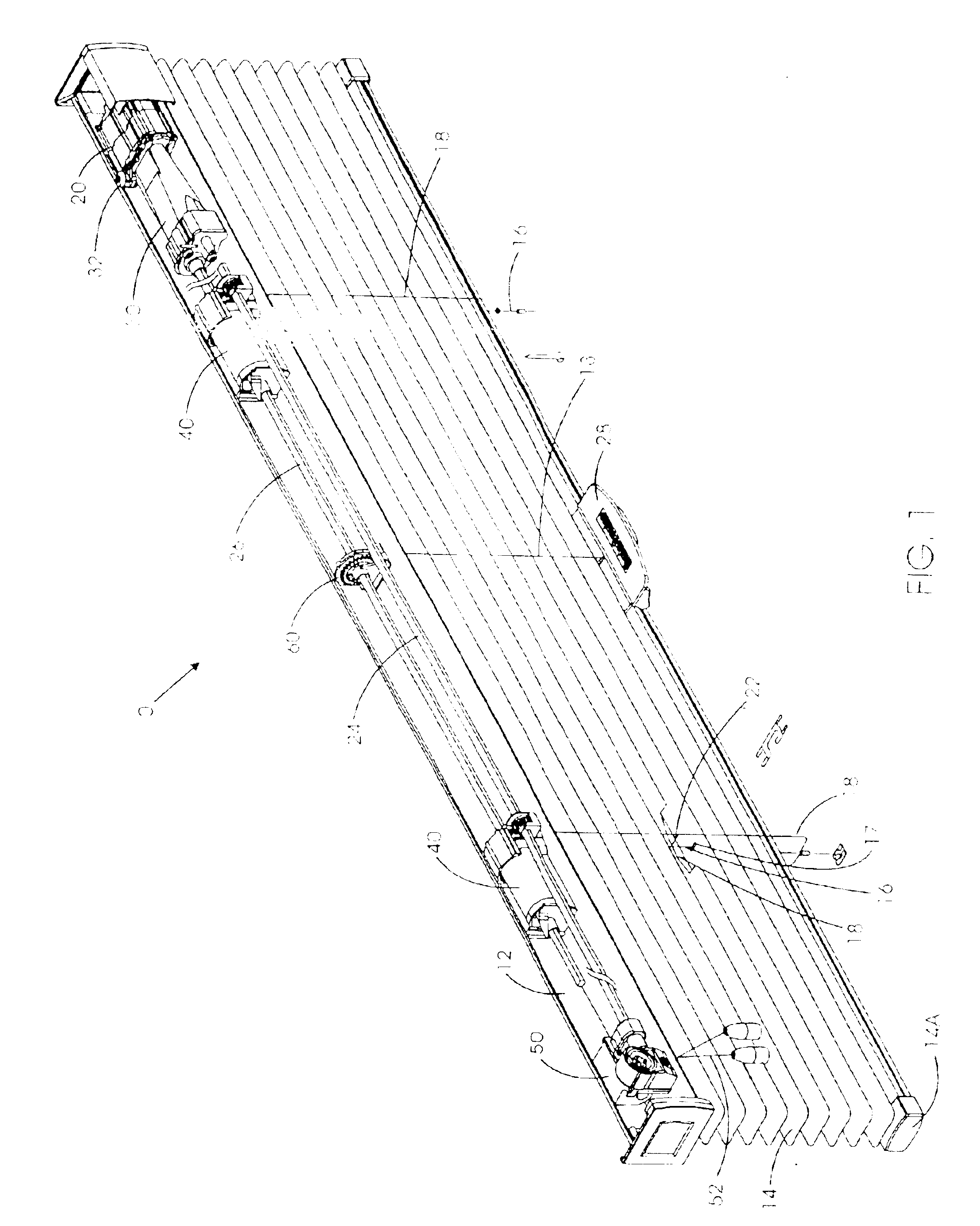
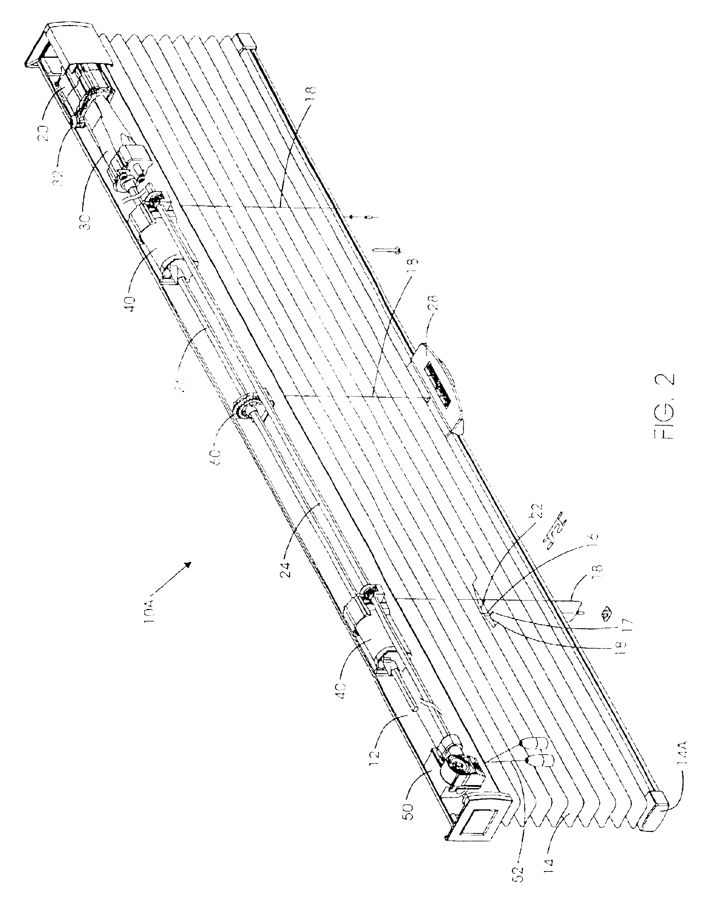
Modular transport system for coverings for architectural openings
a transport system and module technology, applied in the direction of door/window protective devices, building components, constructions, etc., can solve the problems of reducing the gap between the kicker and the spool, not being able to maintain constant force of the coiled spring motor used by the bixler, and wasting a lot of tim
- Summary
- Abstract
- Description
- Claims
- Application Information
AI Technical Summary
Benefits of technology
Problems solved by technology
Method used
Image
Examples
first embodiment
[0373]Typically a 3:1 transmission ratio is enough to handle the load of the lighter weight blinds (smaller blinds or blinds made out of plastic or fabric). However, for higher loads, such as those encountered when handling larger blinds or blinds made out of wood, a higher transmission ratio in the 5:1 range or higher may be required. The 3:1 transmission ratio can be achieved by having a smooth, unthreaded cylinder 402 (with no taper) (As shown in FIG. 65) in connection with a uniformly tapered threaded cone 412 which has a uniform pitch to the threads for its entire length, as was described with respect to the transmission 30. The result is a desirable, very linear power curve. In the 5:1 transmission, however, in order to keep the shafts 402, 412 short and stubby instead of long and slender, both the drive shaft and the driven shaft are tapered (as shown in FIG. 66). This brings in another complication—proper tracking of the cord 454 as described below.
[0374]In order for the tra...
second embodiment
[0480]FIGS. 138-140 show the tilt only module 60A, in which the ladder pulley 62A has a non-cylindrical-profile hollow shaft 63A. In this case, the lift rod 26 not only goes through the hollow shaft 63A but also engages it, such that when the lift rod 26 rotates, it will cause the ladder pulley 62A to rotate as well. In this instance, the tilt cables 18 are not be secured to the ladder pulley 62A, but instead they are draped over the pulley as was discussed for the simultaneous lift / tilt module 500B (See FIG. 127). Now, as the lift rod 26 rotates, the ladder pulley 62A also rotates, pulling one tilt cable 18 up while the tilt cable 18 on the other side of the slats 14 is pushed down so as to close (or open) the slats 14. This action will continue until the lift rod 26 stops, or until the slats 14 reach a fully closed position. At that point, the resistance to continued rotation from the slats 14 will exceed the frictional resistance between the draped tilt cables 18 and the surface ...
third embodiment
[0553]In FIG. 3, this invention, a standard rout product uses a simultaneous lift / tilt module 500B to eliminate the need for the cord tilter module 50 of FIG. 1. As the bottom rail 14A is raised, the lift cords 16 wind onto the lift spools 504B of the lift modules 500B, as has already previously been described. As each lift spool 504B rotates, the frictional resistance between the inside diameter of the shaft 587B of the ladder pulley 583B, and the outside diameter of the stub shaft 536B of the lift spool 504B, as well as the frictional resistance between the front end 526B of the spool 504B and the side of the ladder pulley 583B, will also cause the ladder pulley 583B to rotate, which will also cause the tilt cables 18 of the ladder tape 22 to move, raising one tilt cable 18 while lowering the other tilt cable 18. This action will continue until the bottom rail 14A motion is stopped, or until the slats 14 are fully closed in one direction or the other. Once the slats 14 are fully c...
PUM
 Abstract
Description
Claims
Application Information
 - R&D
- Intellectual Property
- Life Sciences
- Materials
- Tech Scout
- Unparalleled Data Quality
- Higher Quality Content
- 60% Fewer Hallucinations
Browse by: Latest US Patents, China's latest patents, Technical Efficacy Thesaurus, Application Domain, Technology Topic, Popular Technical Reports.
© 2025 PatSnap. All rights reserved.Legal|Privacy policy|Modern Slavery Act Transparency Statement|Sitemap|About US| Contact US: help@patsnap.com


