
Electromagnetic operating device

a technology of operating device and operating device, which is applied in the direction of operating device/releasing device of valve, magnetic body, etc., can solve the problems of increasing the power load to be carried by the coil, and the increase of the power load. , to achieve the effect of increasing the power load, improving the responsiveness, and speeding up at the initial excitation start stag

Inactive Publication Date: 2005-11-29
YUKEN KOGYO
View PDF7 Cites 67 Cited by
  • Summary
  • Abstract
  • Description
  • Claims
  • Application Information

AI Technical Summary

Benefits of technology

The present invention provides an electromagnetic operating device that can speed up at the initial stages of excitation and improve responsiveness without increasing power load on the drive circuit or power supply. This is achieved by using a solenoid coil with a plurality of split coils that can be selectively and independently controlled by an excitation controller. The device can also be adapted for power saving by selectively exciting a limited number of split coils or shutting off the remaining ones. The invention also includes an electromagnetic valve with the electromagnetic operating device and a transmission mechanism for transmitting the mechanical output of the device.

Problems solved by technology

A power loss and electromagnetic induction noise in wiring and each coil also increase as well as an increase in power load to be borne by each of a drive circuit and a power supply for the solenoid device.
Thus, while the use of the solenoid coil reduced in the number of turns is effective in speeding up the operation and improving the responsiveness, a coil that excessively increases in drive current, has been taken as unrealistic in terms of practical use.
However, only a relatively low current value for merely holding the movable core in an attracted state is needed after switching of the valve, and wastage of power cannot be ignored when excitation is continuously carried out with the same excitation current.
However, it is also accompanied by a drawback that since power consumed by the resistor is caused to escape as heat, the effect of performing power saving as viewed from the power supply side is not so obtained, and when such a time limit operation is performed through the use of a semiconductor device such as a transistor or the like, a semiconductor device large in power capacity is needed.

Method used


Image

  • Electromagnetic operating device
  • Electromagnetic operating device
  • Electromagnetic operating device

Examples


Embodiment Construction

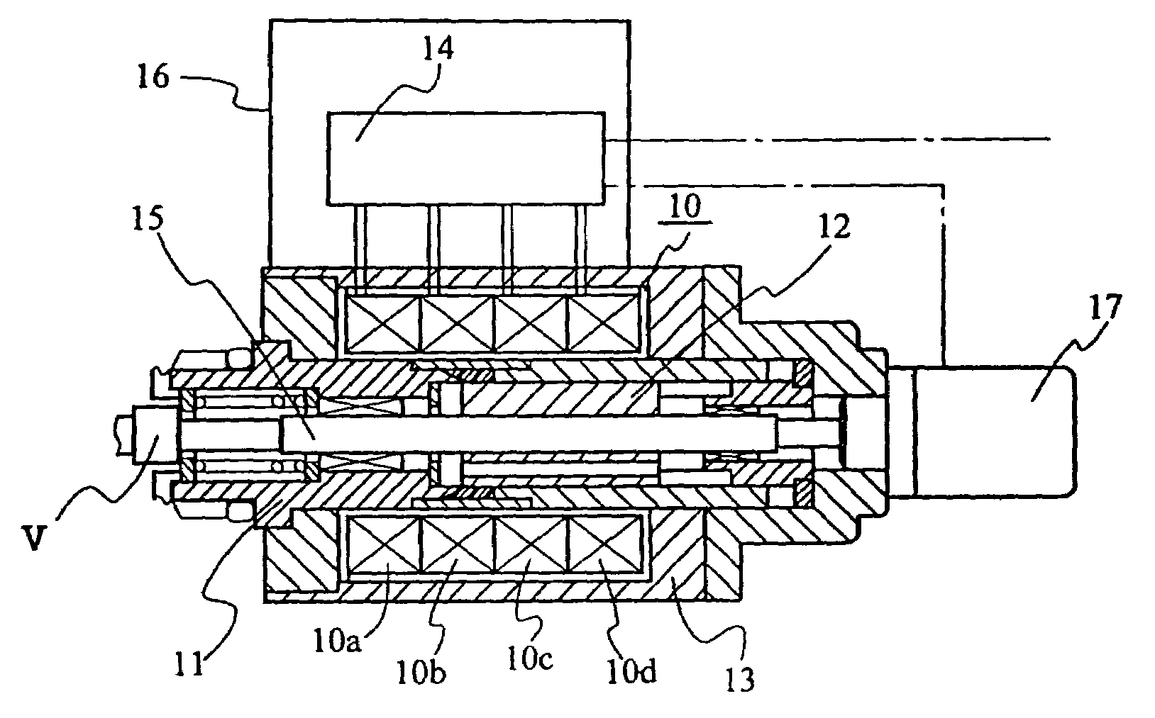
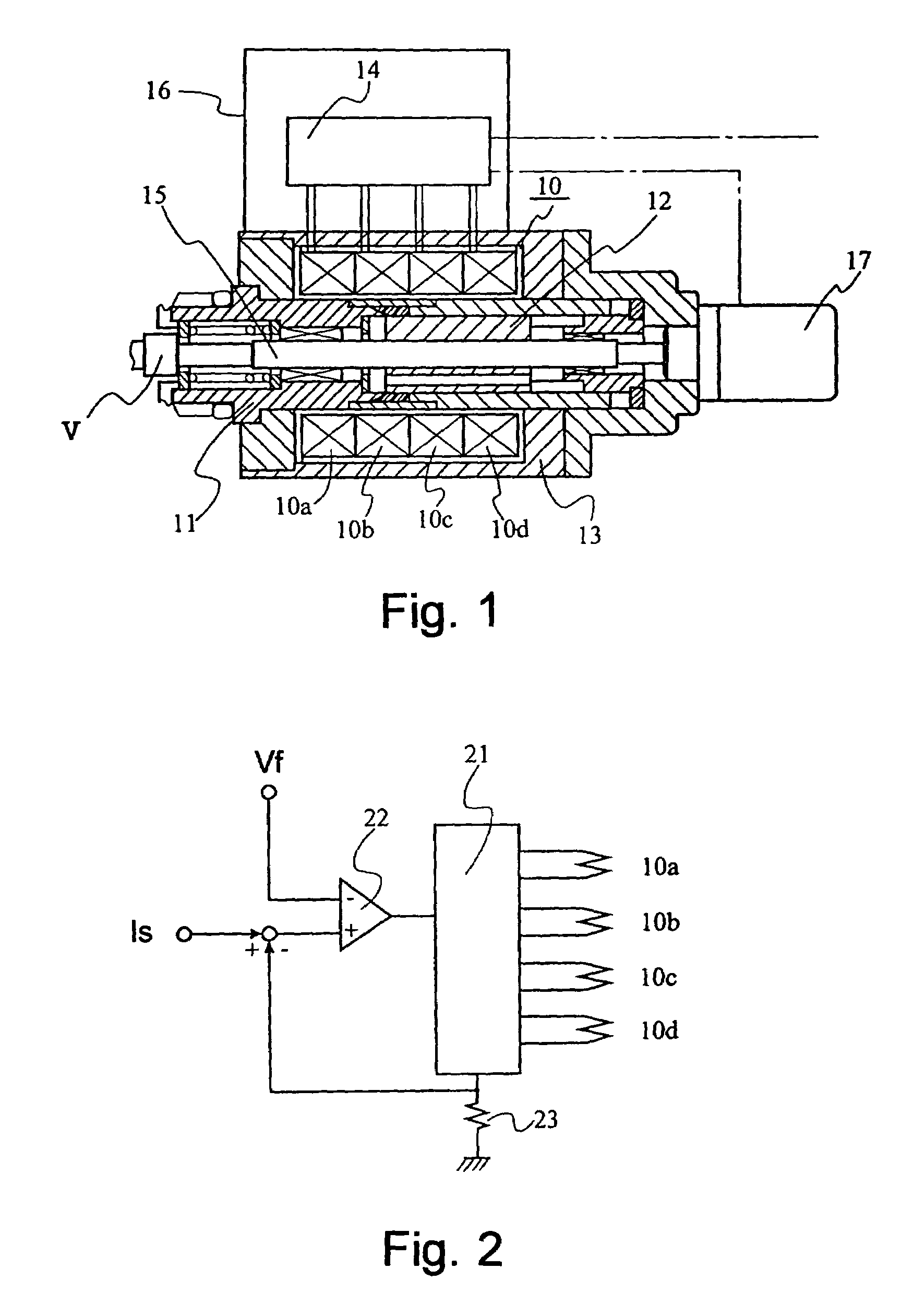
[0036]Preferred embodiments of the present invention will be described hereinafter in conjunction with the accompanying drawings. FIG. 1 shows a schematic configuration of an electromagnetic operating device according to the first embodiment of the present invention. This embodiment illustrates a proportionally-operated type wherein a spool type valve element V of a proportional electromagnetic control valve is driven against a spring force preloaded on the valve element by a well-known return spring.

[0037]As shown in the figure, the electromagnetic operating device constitutes a proportional solenoid device provided with a solenoid coil 10 comprising a plurality of split coils 10a, 10b, 10c and 10d which are electrically independent of one another, an iron or magnetic core structure comprising a fixed core 11, a movable core 12 and a yoke 13 and assembled with the solenoid coil 10 in such a way as to form a magnetic path loop where magnetic fluxes produced from the split coils pass...


PUM

PropertyMeasurementUnit
resistanceaaaaaaaaaa

Abstract

Disclosed is a solenoid type electromagnetic operating device which needs a relatively large current only for a limited short period at an excitation start initial stage and is adapted to achieve the speeding up at an excitation start stage and an improvement in responsiveness as well as power saving without increasing a power load on each of a drive circuit and power supply. The device is used for exerting a mechanical output on a valve element against a spring force, and comprises a solenoid coil composed of a plurality of split coils mutually electrically independent, an iron core structure including a fixed core, a movable core and a yoke and assembled with the solenoid coil so as to form a magnetic path loop through which magnetic fluxes from the split coils pass in common, an excitation controller for selectively switching / controlling the excitation current to each split coil, and a transmission mechanism for transmitting the mechanical output based on the displacement of the movable core magnetically attracted to the fixed core to the valve element when one or more of the split coils are excited.

Description

[0001]This application is a U.S. National Phase Application under 35 USC 371 of International Application PCT / JP00 / 08021 filed Nov. 14, 2000.TECHNICAL FIELD[0002]The present invention relates to an electromagnetic operating device, and more specifically to an electromechanical transducer comprising a solenoid type electromagnet device particularly suitable for economization of power consumption, the speeding up of the operation thereof or an improvement in responsiveness, for driving and operating a valve element of a solenoid operated valve such as a proportional electromagnetic control valve, etc., by a mechanical output against a spring force preloaded on the valve element.BACKGROUND ART[0003]As electromagnetic operating devices for various electromagnetic operated valves such as a directional controll valve, a proportional control valve, etc., there are known various types of electromechanical transducers for respectively exerting a mechanical output on a valve element against a...

Claims


Application Information

Patent Timeline
Patent Type & Authority Patents(United States)
IPC IPC(8): F16K31/06F16K31/72H01F7/16H01F7/18
CPCF16K31/0679H01F7/1607H01F7/1827H01F7/1877H01F2007/1692H01F2007/1888H01F7/1833Y10T137/8242
Inventor NAGANO, TAKUOHBA, KOICHISHINGU, YASUYUKIHIRANO, KENICHI
Owner YUKEN KOGYO
Learn More