
Apparatus and method for operating a master-slave system with a clock signal and a separate phase signal

a master-slave system and clock signal technology, applied in the direction of generating/distributing signals, digital transmission, instruments, etc., can solve the problems of impedance discontinuities on the clock loop, timing problems, and prior art slave devices using this configuration are susceptible to timing skew errors, etc., to improve timing performance in the master-slave system, the effect of reducing the cost and power consumption

Inactive Publication Date: 2005-11-22
RAMBUS INC
View PDF14 Cites 21 Cited by
  • Summary
  • Abstract
  • Description
  • Claims
  • Application Information

AI Technical Summary

Benefits of technology

[0017]The lower “effective frequency” phase signal does not produce standing waves which would introduce timing errors in the master-slave system. The phase signal is processed in the slave devices by known components that minimize expense and power consumption. Thus, the invention provides a low cost solution to improve timing performance in a master-slave system.

Problems solved by technology

Thus, prior art slave devices using this configuration are susceptible to timing skew errors between the frequency signal and the data signal.
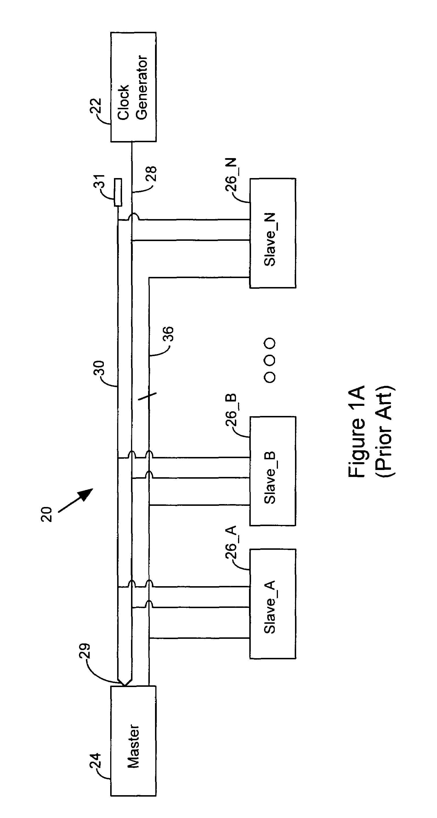
Returning to FIG. 1A, a problem with this prior art system is that there are impedance discontinuities on the clock loop (28, 29, 30).
This meandering delay causes timing problems in the reading and writing of data from and to the data bus 36.
The problem with this solution is that it complicates the configuration of each slave device 26: it makes each slave device 26 more expensive and it results in increased power consumption at each slave device.
Another disadvantage of prior art systems is that attenuation of the clock signal amplitude is difficult to remedy.
Adding buffers or making multiple copies of the clock to reduce attenuation has the undesirable effect of distorting the clock signal phase.
A related disadvantage of prior art systems is that the lengths of the clock signal traces coupled to a given slave device must usually match the length of the datapath between the master and the slave device, complicating system layout.
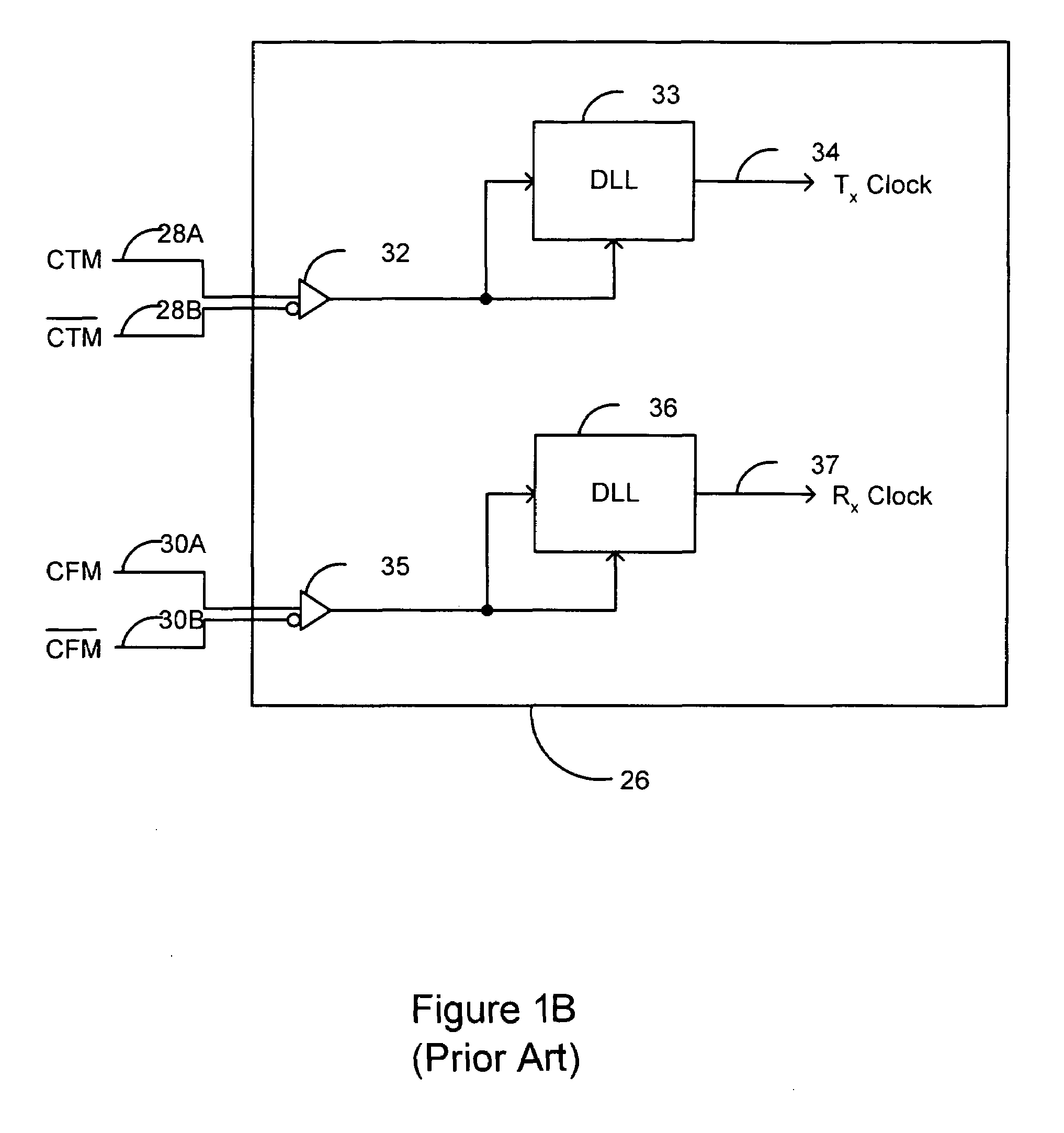
Yet another disadvantage of prior art systems is that the distribution of the clock signal in a differential format, as shown in FIG. 1B, leads to differences between the clock and data reception circuitry within the slave device.
These differences tend to produce undesirable timing skew between the clock and data.

Method used


Image

  • Apparatus and method for operating a master-slave system with a clock signal and a separate phase signal
  • Apparatus and method for operating a master-slave system with a clock signal and a separate phase signal
  • Apparatus and method for operating a master-slave system with a clock signal and a separate phase signal

Examples


Embodiment Construction

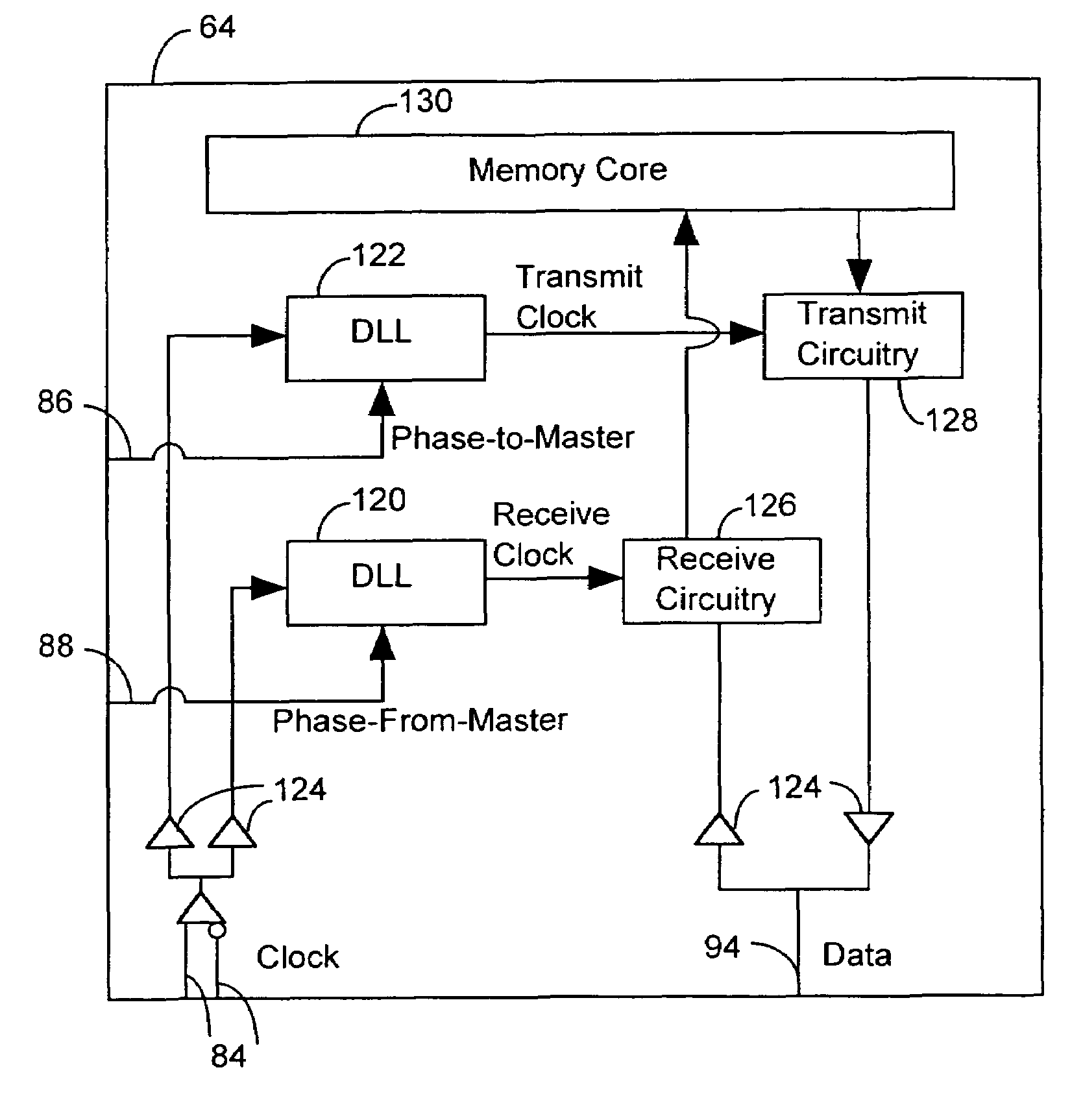
[0031]FIG. 3A illustrates a master-slave system 60 operated with a separate clock signal and phase signal in accordance with an embodiment of the invention. The system 60 includes a master device 62 (e.g., a memory controller) and a set of slave devices 64—A to 64—N (e.g., a set of memory devices): The system utilizes a clock and phase signal generator 70. As its name implies, the clock and phase signal generator 70 produces a clock signal, which is applied to line 72, and a phase signal, which is applied to line 78. The clock and phase signal generator 70 produces two distinct signals: a clock signal and a phase signal. Thus, the clock and phase signal generator 70 can be implemented with two distinct signal generating circuits: a clock generator and a phase reference generator.

[0032]Observe in the prior art system of FIG. 1A that the clock generator 22 generates a single clock signal, not the separate clock and phase signals produced by the clock and phase signal generator 70. In ...


PUM


Abstract

A master-slave system includes a clock and phase signal generator to produce a clock signal at a given frequency and a phase signal at an effective frequency, where the phase signal may or may not be periodic and has an effective frequency less than the given frequency. A clock line is connected to the clock and phase signal generator to carry the clock signal. A phase line is connected to the clock and phase signal generator to carry the phase signal. The phase line includes a phase-to-master path to carry a phase-to-master phase signal and a phase-from-master path to carry a phase-from-master phase signal. A master device is connected to the clock line and the phase line. A data bus is connected to the master device. A slave device is connected to the data bus, the clock line and the phase line. The slave device processes data on the data bus in response to the clock signal and the phase signal.

Description

BRIEF DESCRIPTION OF THE INVENTION[0001]This invention relates generally to digital systems. More particularly, this invention relates to a digital system in which a master device and a set of slave devices exchange data in response to a clock signal and a separate phase signal.BACKGROUND OF THE INVENTION[0002]FIG. 1A is a simplified illustration of a prior art synchronous bus system. The system is described in U.S. Pat. No. 5,432,823, which is assigned to the assignee of the present invention, and is hereby incorporated by reference.[0003]The system 20 of FIG. 1A includes a clock generator 22, a master device 24, and a set of slave devices 26—A through 26—N. A transmission channel is comprised of three components: a clock-to-master path 28, a turn-around path 29, and a clock-from-master path 30. The transmission channel ends at a termination block 31, which may be implemented with a resistor. Each clock pulse from the clock generator 22 traverses from the clock-to-master path 28, t...

Claims


Application Information

Patent Timeline
IPC IPC(8): G11C7/00G11C7/22H03L7/06
CPCG11C7/22G11C7/222H03L7/06
Inventor PERINO, DONALD V.
Owner RAMBUS INC
Learn More