
Reverse link outer loop power control with adaptive compensation

a technology of adaptive compensation and power control, applied in power management, electrical equipment, radio transmission, etc., can solve the problem that the scheme often fails to achieve its objectiv

Inactive Publication Date: 2005-11-15
LUCENT TECH INC
View PDF18 Cites 35 Cited by
  • Summary
  • Abstract
  • Description
  • Claims
  • Application Information

AI Technical Summary

Benefits of technology

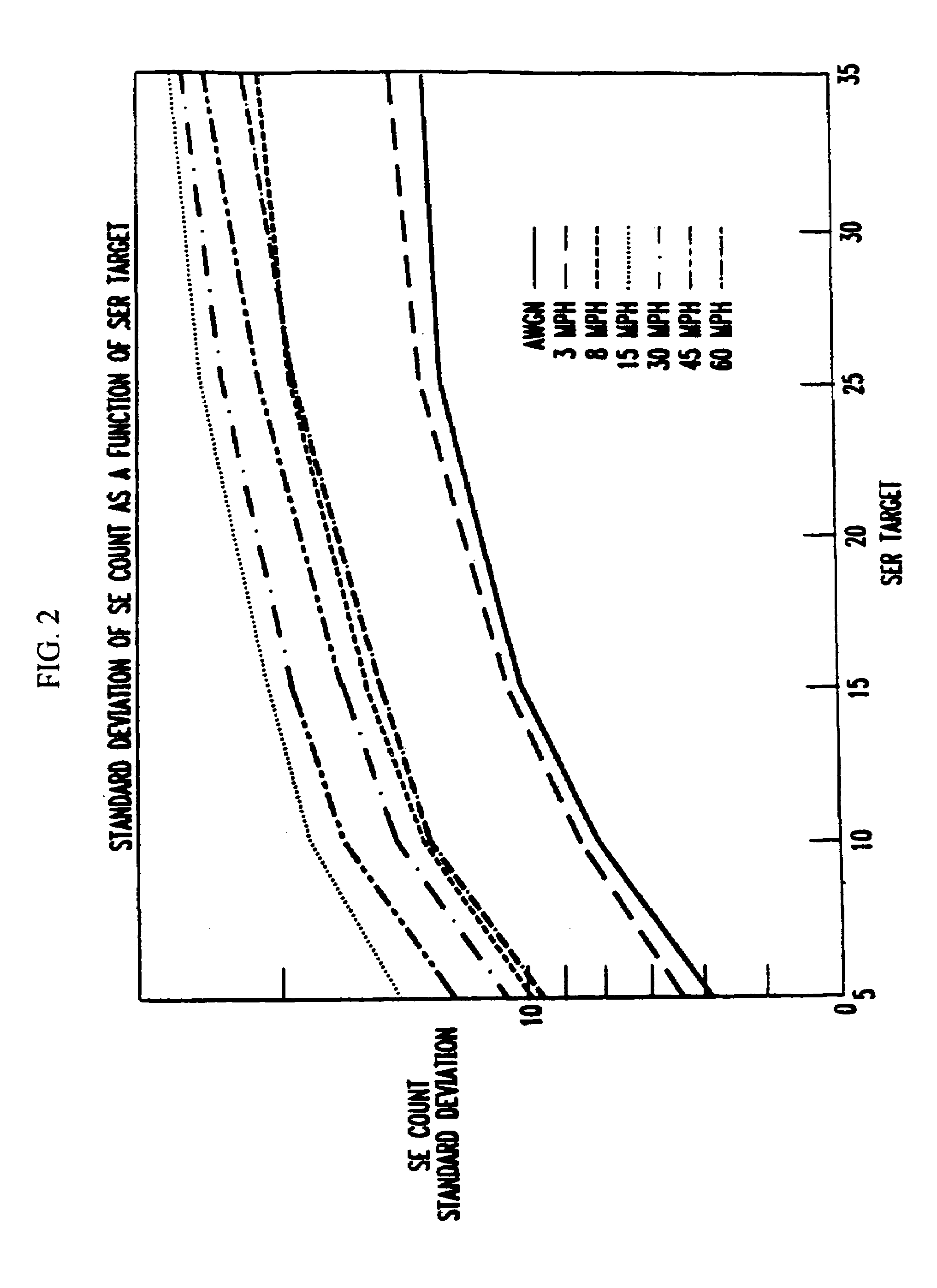
[0012]In another embodiment of the invention, a base station uses a 2nd order statistic, e.g., standard deviation (variance), to identify, or act as a signature of, a particular cellular (wireless) communications environment. The signature is used to set a target symbol error rate appropriate for the current environment. The (Eb / N0)T target is adjusted as a function of a comparison of the symbol error count with a dynamically adjusted SER target. The base station monitors the standard deviation of the symbol error count of a received signal (transmitted from a mobile station). The (Eb / N0)T target is adjusted as a function of the value of the standard deviation. The adjusted (Eb / N0)T target is used to provide power control. As a result, the inventive concept provides a technique to control FER in a variety of cellular communications environments and, at the same time, keep the performance benefits of a SER based technique.

Problems solved by technology

We have observed that even in a steady environment where the statistical nature of the signal fluctuations do not change with time, even the use of an instantaneous BER estimate cannot always set the target SNR at a level where the actual average BER is close to the desired BER.
As a consequence, when the desired end-user quality metric is the mean or average BER, this scheme often fails to achieve its objective.

Method used


Image

  • Reverse link outer loop power control with adaptive compensation
  • Reverse link outer loop power control with adaptive compensation
  • Reverse link outer loop power control with adaptive compensation

Examples


Embodiment Construction

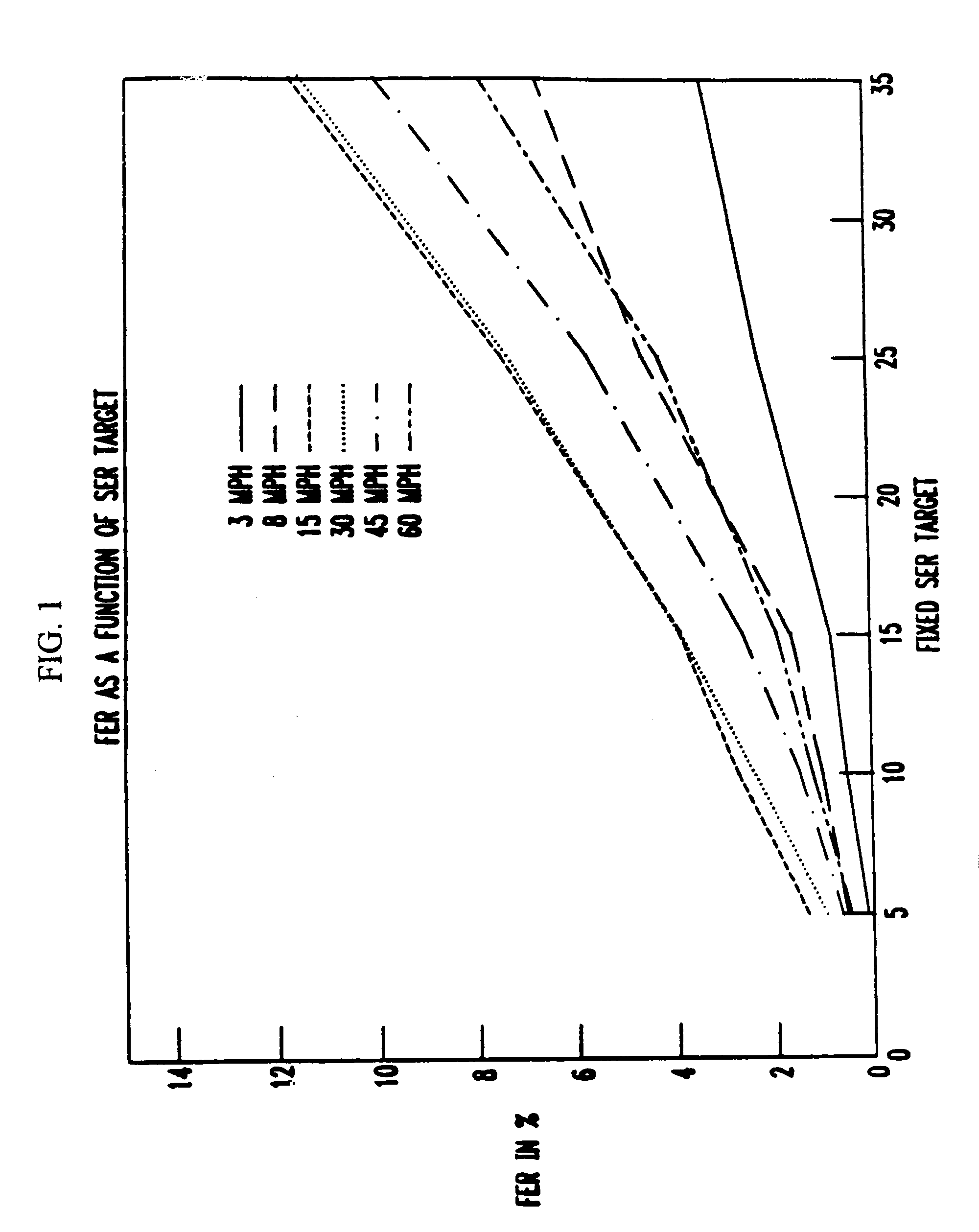
[0020]Before describing the inventive concept, a short description of a fixed symbol error rate (SER) target ROLPC technique is provided. Following this section, the performance results of a simulation of the Fixed SER target ROLPC technique is shown upon which the inventive concept is based. After this performance-related section, the inventive concept is presented.

Fixed SER Target ROLPC

[0021]The core of this technique, assuming only full rate frames have been received and that no erasures have occurred, is described below. (It should be noted that dealing with partial rate frames and frame erasures leading to the loss of the rate estimate can be done in a number of ways. For example, partial rate frames could use smaller step sizes for making changes in the (Eb / N0)T target, and, if the rate information is unavailable because of a frame erasure, the last available rate parameter may be used as an estimate for the current frame rate.)

[0022]The following definitions are used:[0023]TS...


PUM


Abstract

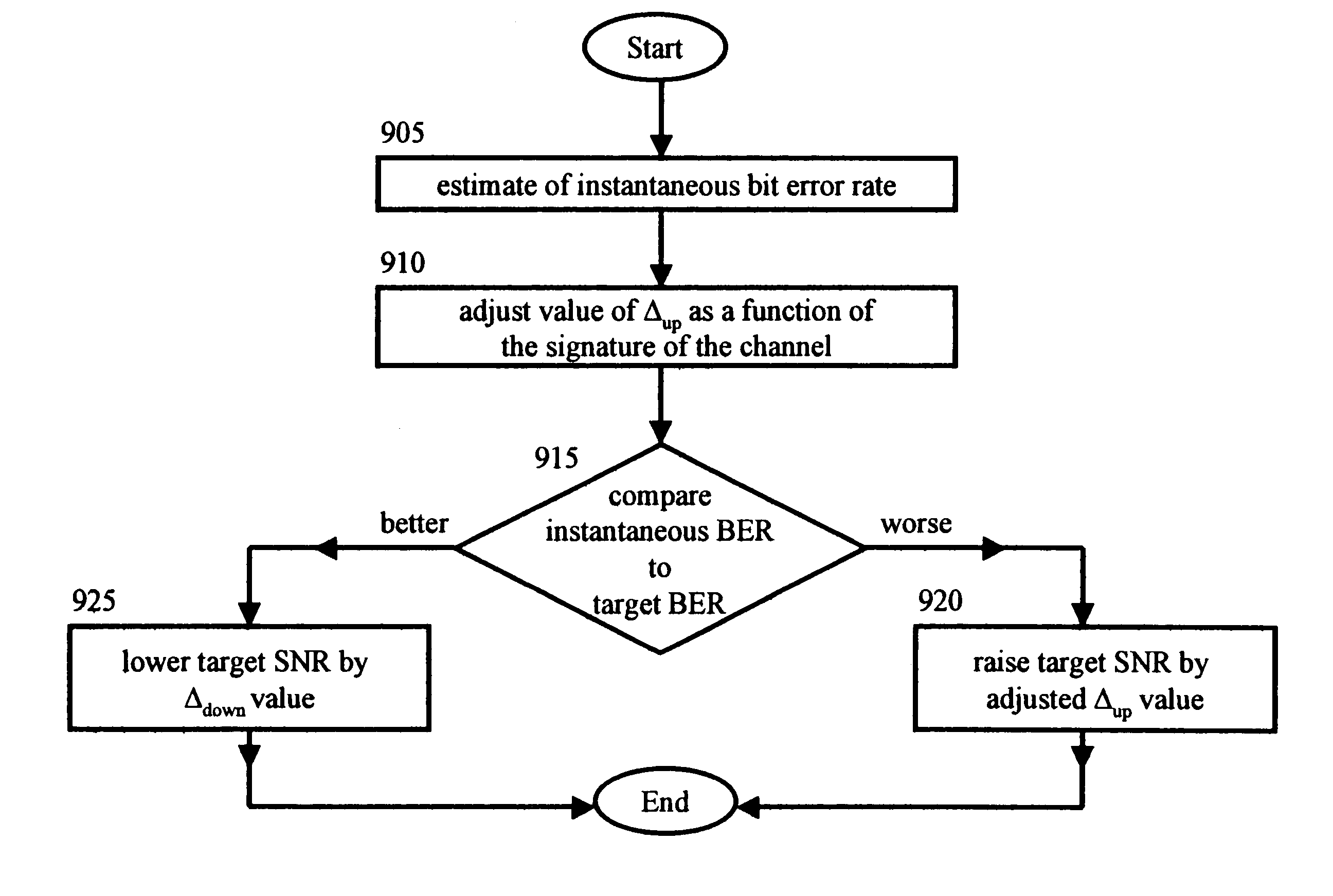
In a wireless communications system, a base station employs a bit error rate (BER) based Reverse Outer Loop Power Control (ROLPC) technique. The ROLPC technique uses either instantaneous or weakly filtered values of the BER for comparison with a BER target value for adjusting a target signal-to-noise ratio (SNR). The BER target value is varied as a function of a second order statistic (e.g. variance, standard deviation) of the received SNR. In another embodiment, a symbol error count based ROLPC technique uses adaptive SER targets. In particular, a base station uses a 2nd order statistic, e.g., standard deviation (variance), to identify, or act as a signature of, a particular cellular (wireless) communications environment. The base station monitors the standard deviation of the symbol error count of a received signal (transmitted from a mobile station). The target signal-to-noise ratio ((Eb / N0)T) of this received signal is adjusted as a function of the value of the standard deviation and the adjusted (Eb / N0)T target is used to provide power control.

Description

[0001]This is a Continuation-In-Part of application Ser. No. 09 / 052,696 filed Mar. 31, 1998 now U.S. Pat. No. 6,434,124.CROSS-REFERENCE TO RELATED APPLICATIONS[0002]Related subject matter is disclosed in the co-pending, commonly assigned, U.S. Patent application of Rege, entitled “A Non-Adaptive Symbol Error Count Based Technique for CDMA Reverse Link Outer Loop Power Control,” application Ser. No. 09 / 052,581, filed on Mar. 31, 1998.FIELD OF THE INVENTION[0003]This invention relates generally to communications and, more particularly, to wireless systems.BACKGROUND OF THE INVENTION[0004]Current and emerging standards for commercial wireless communication systems based on the Code Division Multiple Access CDMA technology (e.g. IS-95, CDMA2000, UMTS) include a sophisticated scheme for control of reverse link transmit power. The overall power control scheme for the reverse link is organized in two layers. The inner layer is called Reverse Inner Loop Power Control (RILPC), while the oute...

Claims


Application Information

Patent Timeline
Patent Type & Authority Patents(United States)
IPC IPC(8): H04B7/00H04B7/005
CPCH04W52/12H04W52/146H04W52/20H04W52/225
Inventor MONOGIOUDIS, PANTELISREGE, KIRAN MSAMPATH, ASHWIN
Owner LUCENT TECH INC
Learn More