
Induction exhaust system

Inactive Publication Date: 2005-11-15
CAMPBELL MONTY ALLEN
View PDF7 Cites 7 Cited by
  • Summary
  • Abstract
  • Description
  • Claims
  • Application Information

AI Technical Summary

Benefits of technology

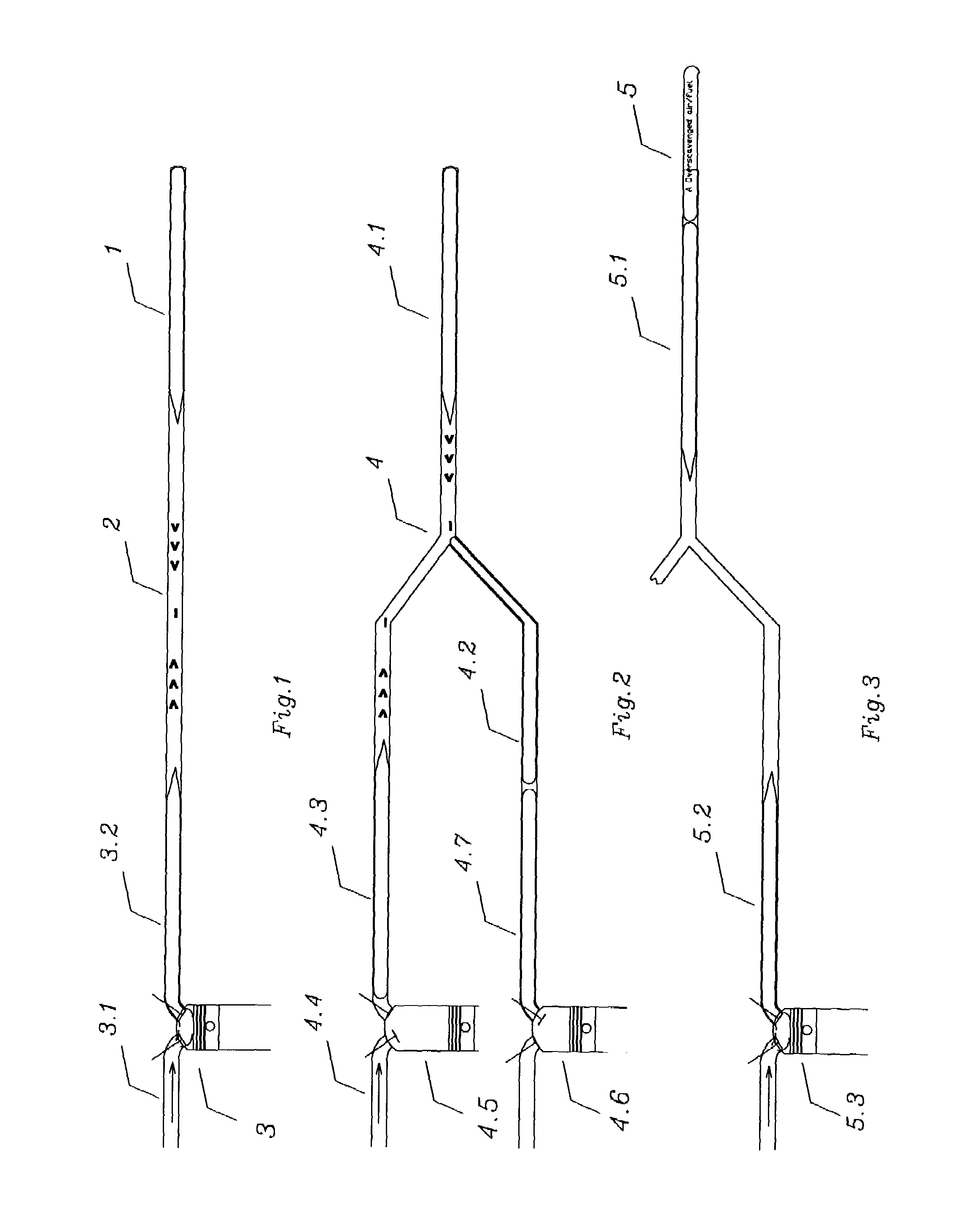
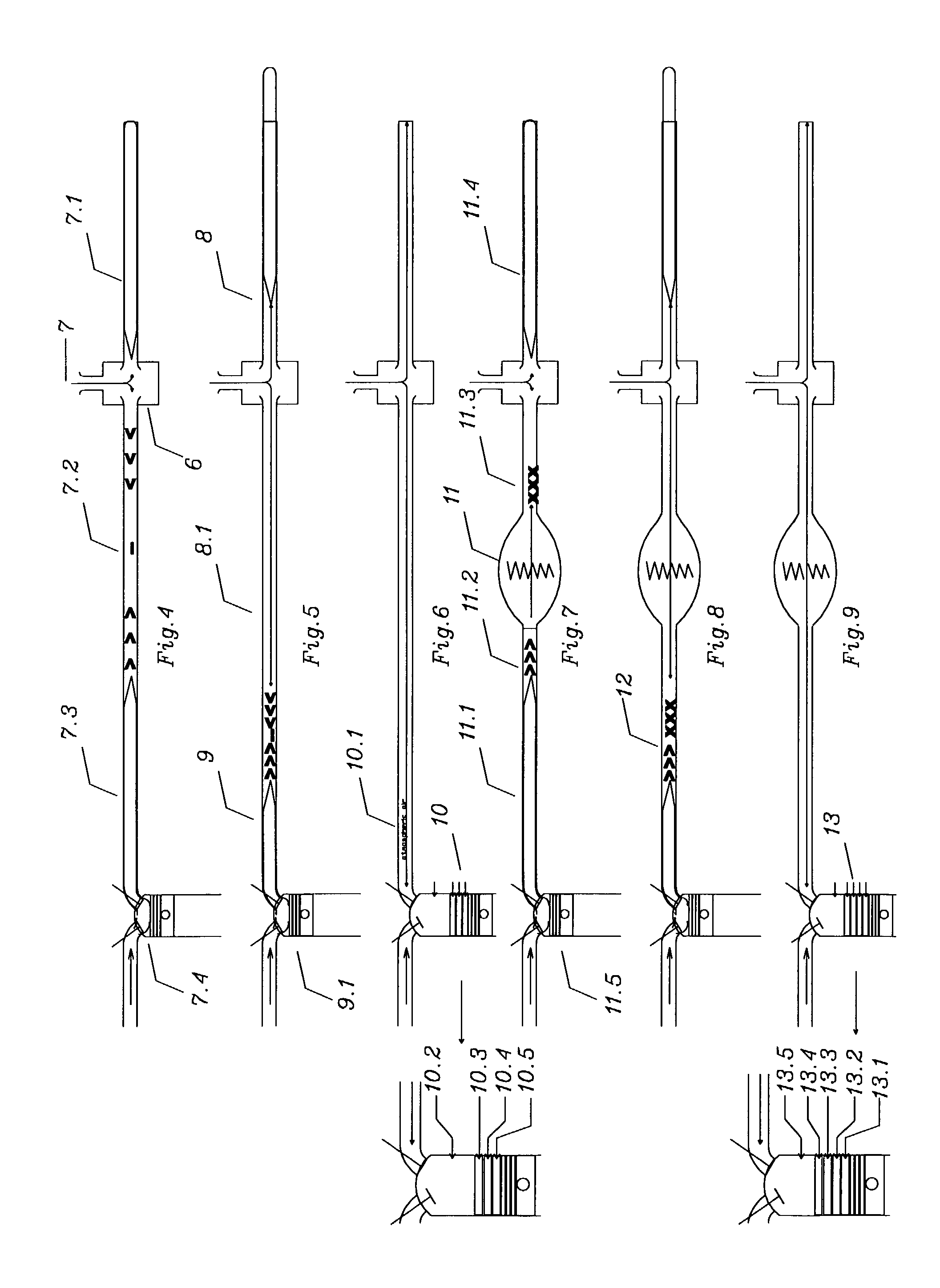
[0008]Therefore the objects of the present invention are as follows: to provide an induction exhaust system for an internal combustion engine which improves the thermal-mechanical conversion efficiency of the engine over conventional exhaust systems by; creating precisely timed events; 1) a scavenge event (where exhaust gasses are removed from cylinders of the engine), 2) a vacuum break event (to stop overscavenging of unburned air fuel), and 3) a pressure event wherein energetic free radicals, unburned air fuel and other desired matter are inducted via the engine's exhaust port. Such timed events increase engine efficiency and reduce fuel consumption and emissions.

Problems solved by technology

Horsepower is lost due to reduced dynamic cylinder pressure.
Fuel economy is lost due to the quantity of fuel and free radicals left unburned.

Method used


Image

  • Induction exhaust system
  • Induction exhaust system
  • Induction exhaust system

Examples


Embodiment Construction

[0031]FIG. 17 is a top plan view showing an induction exhaust system according to the preferred embodiment of the invention. An internal combustion engine (not shown) having at least two sequentially timed cylinders, and at least two exhaust flow manifolds, or collectors, and usually at least two catalytic converters, communicate flow with system inlet pipes 45&46 respectively. Upon the arrival of the first exhaust pulse from such engine, it enters inlet pipe 45. Because the exhaust pulse is a very energetic, high temperature mass, released from high cylinder pressures by the operation of the exhaust valve, it reaches a high escape velocity. The exhaust cycle starts with the opening of the exhaust valve, which allows remaining combustion gas thermal energy, cylinder pressure, to be converted into a high kinetic energy gas exhaust pulse column traveling out the exhaust port, into herein described induction exhaust system. Such, first exhaust pulse enters such induction exhaust at tub...


PUM


Abstract

A induction exhaust system, for an internal combustion engine, capable of the multi step processes of 1) scavenging the chamber of exhaust gases and free radicals, 2) breaking the scavenge vacuum wave behind each energetic exhaust pulse, releasing said free radicals and the overscavenged air fuel vacuumed from the intake manifold during valve overlap, and 3) induction of such free radicals, unburned fuel, and fresh matter including atmospheric air. Such multi step process 1) relatively improves the fuel efficiency of such engines by reducing the wasted potential energy normally expelled by exhaust systems; unburned fuel, sound pressure energy, waste heat energy, energy rich free radicals formed by incomplete combustion, and energy rich catalytic converter products rich in potential energy that can be further combusted via induction, 2) increases catalytic converter efficiency by forcing unburned air fuel and free radicals to make multiple passes through such converter, thereby increasing residency time, 3) reduces emissions of undesirable compounds and free radicals via induction, 4) improves relative effective octane rating of fuel used by creating a unique composition of matter that acts to refract and reflect sonic detonation shock waves, disrupting and disbursing them, reducing detonation, thereby improving combustion efficiency, and 5) allows a new means to direct combustion process products and / or remove undesirable products, and / or introduce desirable matter into a combustion chamber, allowing further alteration of such unique composition of matter layered on top of such engine's prime mover combustion surface, and 6)including an adaptive means to dynamically optimize its function.

Description

CROSS REFERENCE TO RELATED APPLICATIONS[0001]None.STATEMENT REGARDING FEDERAL SPONSORED R & D[0002]None.REFERENCE TO SEQUENCE LISTING[0003]None.BACKGROUND OF THE INVENTION[0004]1. Technical Field[0005]This invention relates generally to exhaust systems for internal combustion engines.[0006]2. Description of Related Art[0007]In the early days of exhaust development, when flat head engines were common, scavenge resonant exhaust systems helped to remove residual exhaust gases from the combustion chamber & helped to initiate intake flow into the combustion chamber. Scavenge has evolved into expanding tube extractors, anti-reversion mufflers and structures to prevent loss of scavenge vacuum at low rpms. During this time, cylinder head design has evolved from flat heads to overhead designs incorporating three, four, five and even eight valve per cylinder designs. Combining state of the art scavenge technology with state of the art head designs creates “overscavenge;” a situation where raw...

Claims


Application Information

Patent Timeline
IPC IPC(8): F02B27/00F02B27/04
CPCF02B27/04Y02T10/146Y02T10/16Y02T10/12
Inventor CAMPBELL, MONTY ALLEN
Owner CAMPBELL MONTY ALLEN
Learn More