Allograft implant cutting machine

Active Publication Date: 2005-11-08
ALPHATEC SPINE INC
View PDF24 Cites 62 Cited by
  • Summary
  • Abstract
  • Description
  • Claims
  • Application Information

AI Technical Summary

Benefits of technology

[0019]The mandrel located on the stationary base plate slidably receives over it the hollow cylindrical cutter attached to the horizontal upper plate. To operate the apparatus, a segment of bone to be shaped is placed upon the mandrel and on the table and downward pressure is applied to the horizontal upper plate so that the hollow cylindrical cutting blade is driven through the allograft bone blank. The combination of the vertical guide posts and the bushings on the horizontal upper plate function to keep the path traveled by the hollow cylindrical cutting blade substantially parallel to the longitudinal axis of the mandrel, which in the preferred embodiment is vertical. The hollow cylindrical cutting blade, mandrel, and table, collectively referred to as a matched cutting set, may exist in a series of similar sizes defined by at least one size-characterizing dimension.

Problems solved by technology

Frequently, however, accident trauma, degenerative disc disease, and other pathogenesis can compromise all or a portion of the disc's ability to provide mechanical support and integrity.
Prior art devices of this sort have shown very mixed results.
However, use of autograft bone has serious limitations.
The use of the patient's own bone to fill the space is less than optimal in that bone obtained from the patient requires an additional surgery site, additional healing and risk of infection, and is available only in relatively small amounts.
The latter disadvantage is especially acute when more than one disc must be replaced or when diseased vertebrae themselves must be replaced.
In particular, cancellous or trabecular bone has a cellular structure which makes such bone difficult to handle.
Cutting such a substance cleanly and precisely is obviously a challenge.
Prior art or obvious methods of shaping such a substance would most likely produce a mushy or crumbled unusable mass.
There is minimal prior art relevant to the tools and machinery for the precision fashioning of allograft implants.

Method used


Image

  • Allograft implant cutting machine
  • Allograft implant cutting machine
  • Allograft implant cutting machine

Examples


Embodiment Construction

[0115]The present invention is an apparatus for producing bone implants of various shapes and sizes. The production process consists of cutting the implants from human donor bone, also referred to herein as allograft bone.

[0116]The apparatus described herein is primarily intended for use in the rapid processing of harvested human donor bones. It provides a precision cut to standard sizes so as to provide the proper fit of the graft during surgical implantation.

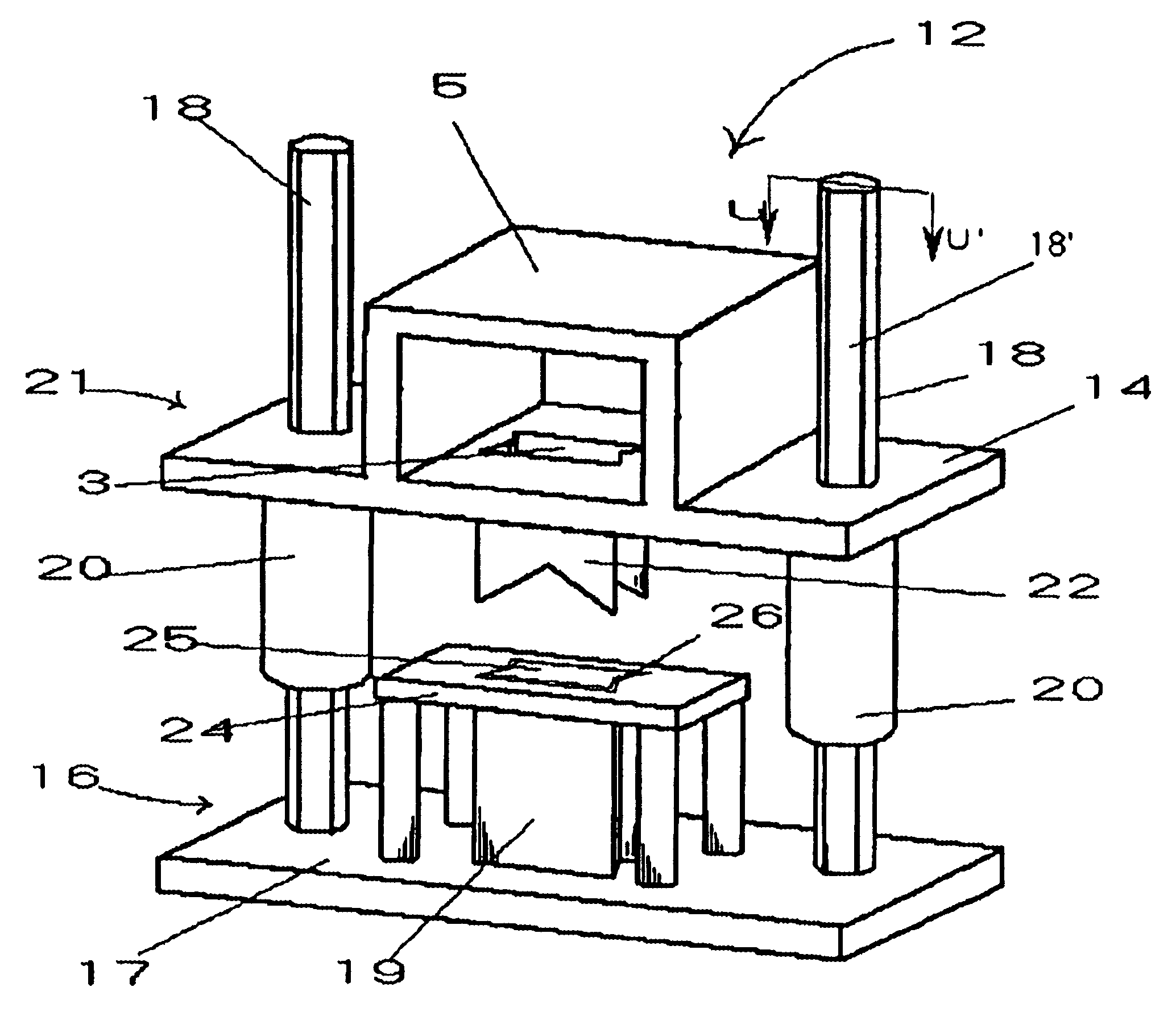
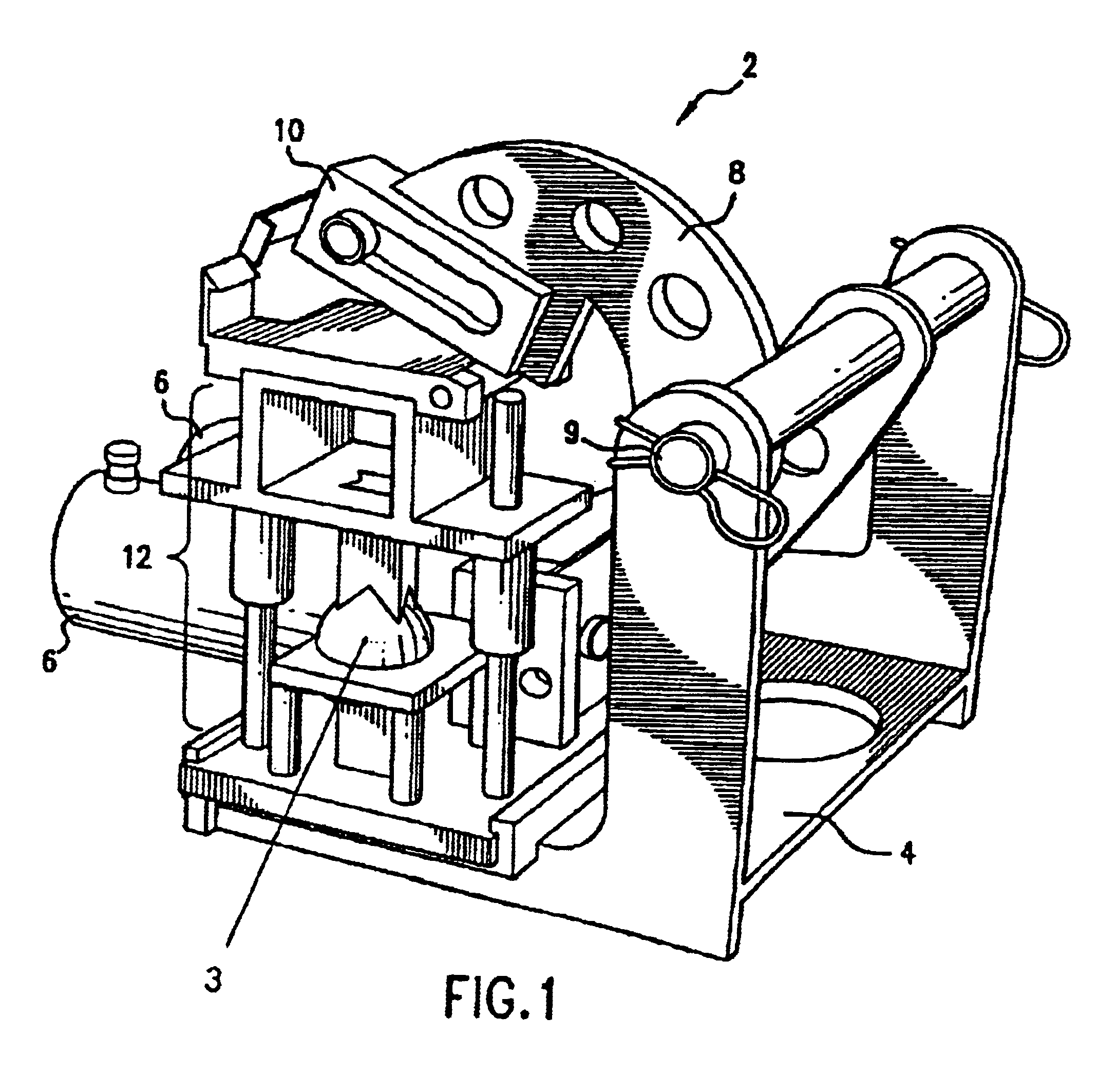
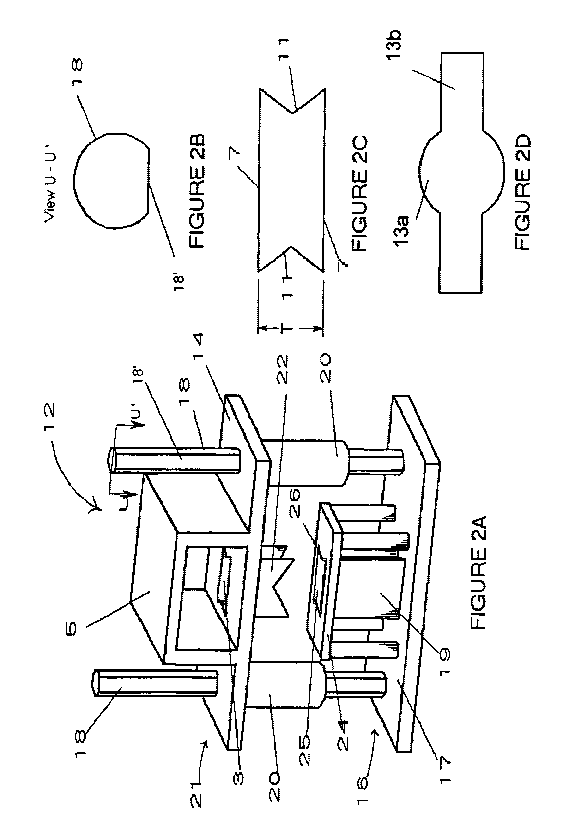
[0117]The bone cutting apparatus of the present invention consists of a press and a series of cutting die sets in which special hollow cylindrical cutting blades are mounted in a way intended to allow the cutting blade to descend over a matchingly shaped but stationary and vertically oriented mandrel. The mandrel has a substantially flat top held in position by vertical support and is surrounded by a table with a top which has an opening matched in shape to the cross-section of the mandrel but with its perimeter displaced outw...


PUM


Abstract

The present invention is an apparatus for cutting allograft bone implants from donor bone. Die sets of standard sizes are installed in a press. Donor bone is then placed in position between the upper and the lower parts of a matched cutting set comprising a hollow cylindrical cutting blade, a mandrel, and a table which establishes a gap around the mandrel which guides the blade. After the bone to be shaped has been properly placed, a shaped cutting blade is driven through the donor bone, producing a precisely shaped allograft implant. The invention provides for rapid change out of blades, rapid cleaning, and easy maintenance.

Description

FIELD OF THE INVENTION[0001]The present invention relates to implants to be placed into the human body to replace, at least structurally, portions of the body removed because of damage or disease. It also relates to fabricating such implants from tissue donated from deceased persons, commonly referred to as allograft tissue, and in particular it relates to the tools or machines used to fabricate such implants from allograft tissue. It further relates to implants used to replace a portion of the bony structure of the human body, more especially to implants which are designed to fill the intervertebral space created by the partial or complete removal of a damaged spinal disc. Finally and specifically it relates to the apparatus for and method of creating intervertebral implants from allograft bone.BACKGROUND OF THE INVENTION[0002]Natural intervertebral spinal discs serve, among other things, as cushions and shock absorbers for columnar spinal loadings. In addition, they serve to prese...

Claims


Application Information

Patent Timeline
IPC IPC(8): A61F2/46A61B17/16A61F2/28A61F2/44
CPCA61F2/4644A61B17/1635A61B17/1671A61F2/442A61F2002/2839A61F2002/4649
Inventor GATTURNA, ROLAND F.SENNETT, ANDREW R.FAHERTY, RICHARDWHIPPLE, DALE E.
Owner ALPHATEC SPINE INC
Why Eureka
Try Eureka