Respiratory equipment spacer assembly

a spacer and respiratory equipment technology, applied in the field of respiratory equipment, can solve the problems of patient considerable physical discomfort, constant loss of patients, and associated with the use of large-volume spacers, and achieve the effects of reducing compressibility effects, improving drug delivery, and reducing volum

Inactive Publication Date: 2005-11-08
SALTER LABS
View PDF24 Cites 18 Cited by
  • Summary
  • Abstract
  • Description
  • Claims
  • Application Information

AI Technical Summary

Benefits of technology

[0008]It is an object of this invention to provide an improved delivery of drug from an MDI to an intubated patient. It is a further object of this invention to provide a spacer of smaller volume to reduce the compressibility effects. It is a further object to provide a spacer of smaller weight to reduce the load applied to the tubing attached to the patient. It is a further object to provide a spacer that efficiently uses all of its internal volume to evaporate more of the propellant before it can impact the walls of the spacer and inhibit drug delivery to the patient. It is a further object to provide a novel nozzle that minimizes the distance that the plume will travel before the propellant is evaporated. It is a further object of this invention to provide a device that can be used for both MDI delivery and the delivery of aerosolized medication from a nebulizer. The present invention provides a spacer assembly suitable for disposition into the respiratory gas stream of a patient, especially an intubated patient attached to a ventilator. The spacer assembly is preferably capable of dispensing mists of aerosolized drugs from an MDI canister as well as nebulized medications from a small volume nebulizer. The spacer assembly preferably comprises a body including an expansion chamber having an inlet and an outlet adapted for connecting the spacer assembly to the air flow tubing of a conventional ventilator or other respiratory equipment operable to deliver a pressurized flow of therapeutic respiratory gas.
[0009]The expansion chamber preferably includes a first opening for receiving an MDI nozzle assembly and a second opening for receiving a discharge outlet of a conventional nebulizer or the like. The second opening is preferably sealed by a spring-biased valve or the like when the spacer body is disconnected from a nebulizer. According to a preferred embodiment, the MDI nozzle assembly includes multiple, radially arranged channels terminating in outlet ports which collectively function to dispense liquid propellant-borne medication in a diffuse, gentle, generally umbrella shaped mist or plume of finely atomized drops which allows the propellant to rapidly evaporate upon discharge into the expansion chamber. In so doing, the volume of the expansion chamber and, thus, the outer dimensions and weight of the spacer assembly body may be reduced. By virtue of the compact size of the spacer assembly body, the medication is more efficaciously delivered to the patient. More specifically, less medication is wasted by virtue of impingement of unevaporated medication laden droplets on the interior walls of the spacer body. And, surplus compressible volume is eliminated from the breathing circuit.
[0010]The combined benefits realized by the cooperating structural features of the spacer assembly include, without limitation, superior performance and enhanced patient comfort in a lightweight compact device which may be readily connected to the ventilator tubing or the breathing circuit of any suitable therapeutic respiratory equipment heretofore known in the art.

Problems solved by technology

A major problem with MDI ventilator dispensers is that the expanding plume, consisting of unevaporated droplets containing drug particles, impinges upon the walls of the ventilator circuit and remains there, forever lost to the patient.
There are, however, several disadvantages associated with use of large-volume spacers.
Their weight tends to pull on the ventilator tubing which is inserted into the patient's trachea which may cause the patient considerable physical discomfort.
The volume of the spacer is also a hindrance to optimal air flow to the patient because the spacer adds needless volume to the circuit.
And, in collapsible versions of a large-volume spacer, such as described in U.S. Pat. No. 4,938,210 the spacer may be difficult to open once it has been collapsed.

Method used


Image

  • Respiratory equipment spacer assembly
  • Respiratory equipment spacer assembly
  • Respiratory equipment spacer assembly

Examples


Embodiment Construction

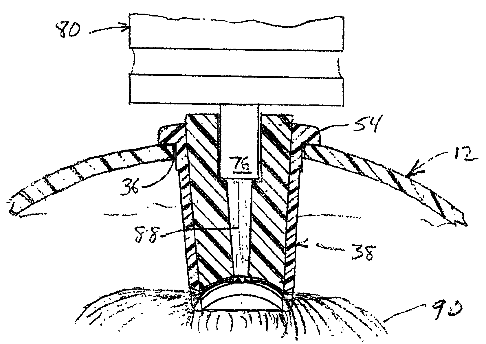
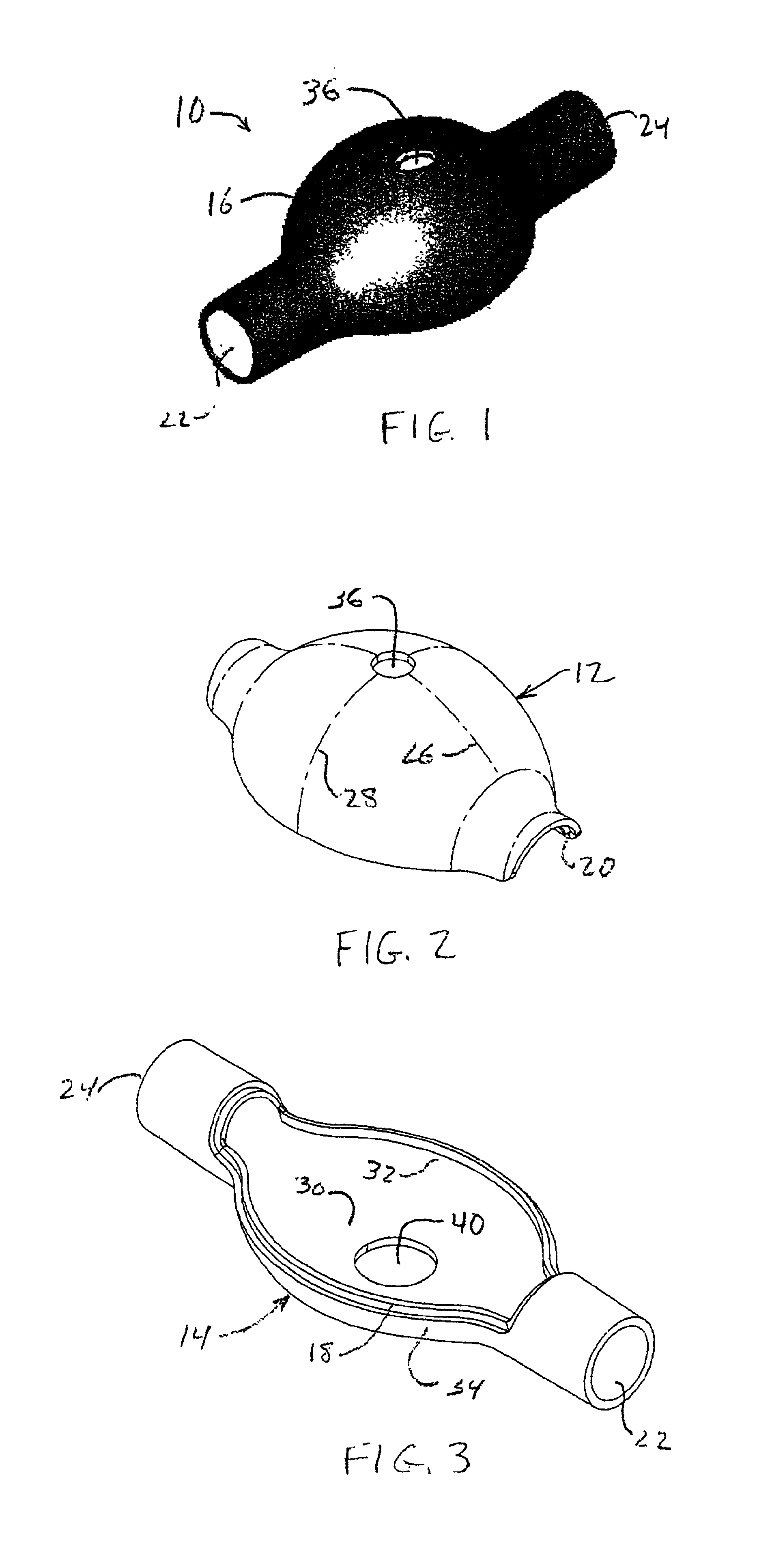
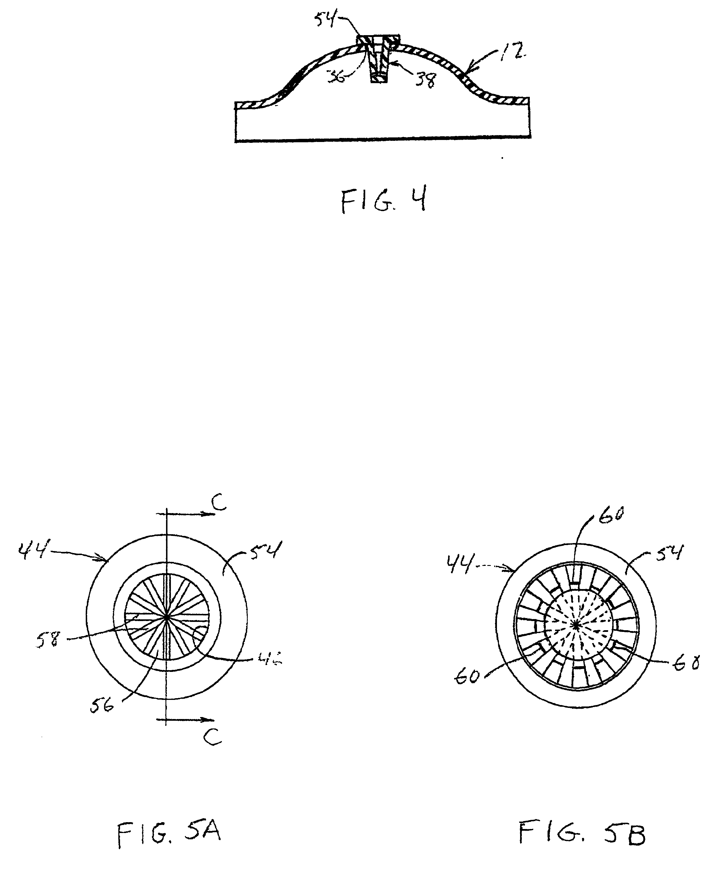
[0024]Referring to FIGS. 1-4 collectively, there is shown a presently preferred construction of a ventilator spacer body number 10 (FIG. 1), including a first portion 12 thereof (FIG. 2) and a second portion 14 thereof (FIG. 3), of the ventilator spacer assembly of the present invention. When assembled, the body member 10 defines a bulbous yet compact medicament expansion chamber. Preferably, the central region 16 of body member 10 is at least semi-spheroidal with the first portion 12 defining an outwardly bulging profile and the second portion 14 defining a predominantly flat profile, whereby central region 16 assumes a generally turtle shell shape. First and second portions 12, 14 of body member 10 may be fabricated from any suitable rigid to substantially rigid metallic or plastic material. Presently preferred materials include ABS, polycarbonate or the like. To facilitate alignment and assembly of the first and second portions 12, 14 one of the first and second body portions is ...


PUM


Abstract

A spacer assembly for a ventilator or other respiratory equipment for dispensing aerosol drugs from metered dose inhaler (MDI) canisters or nebulized drugs from a nebulizer into a respiratory gas stream delivered from a ventilator or other respiratory equipment connected to a patient. The improvements involve optimizing the shape of the spacer assembly body member and providing an efficient MDI nozzle assembly to allow maximal evaporation of the propellant before the propellant droplets impact the walls of the body member while providing a compact volume for directing the output of an MDI canister or a nebulizer into the gas stream.

Description

FIELD OF THE INVENTION[0001]The invention relates generally to respiratory apparatus and particularly to a device that can dispense a drug from a metered dose inhaler (MDI) canister into a stream of air supplied through the inspiratory path between respiratory equipment and a patient, for example, between a ventilator and an endotracheal tube in the trachea of a patient. The device is also preferably capable of introducing aerosolized medication from a nebulizer into the same air stream.BACKGROUND OF THE INVENTION[0002]Drugs dispensed from MDIs usually consist of very finely divided particles, typically in the 1 to 8 micron range. The medication particles are suspended in liquid propellant such as Freon or the like which is under pressure in the MDI canister. Upon actuation, a metered dose of the drug and propellant is ejected through the outlet tube of the canister and, in the prior art, out through one or at most two ports or orifices that are aimed in the longitudinal direction o...

Claims


Application Information

Patent Timeline
Patent Type & Authority Patents(United States)
IPC IPC(8): A61M15/00A61M16/10A61M16/20A61M16/16A61M16/00A61M11/00A61M16/08
CPCA61M15/0086A61M16/08A61M16/20A61M15/009A61M15/0088
Inventor SLADEK, DAVID T.
Owner SALTER LABS
Why Eureka
Try Eureka