
Chemical delivery device

a chemical delivery and controlled release technology, applied in the direction of pill delivery, pharmaceutical non-active ingredients, coatings, etc., can solve the problems of poor patient compliance, ghost residues, and standard tablets, and achieve the effects of easy modulation, increased mechanical strength, and added mechanical strength and stability

Inactive Publication Date: 2005-11-01
MISTRAL PHARMA
View PDF18 Cites 22 Cited by
  • Summary
  • Abstract
  • Description
  • Claims
  • Application Information

AI Technical Summary

Benefits of technology

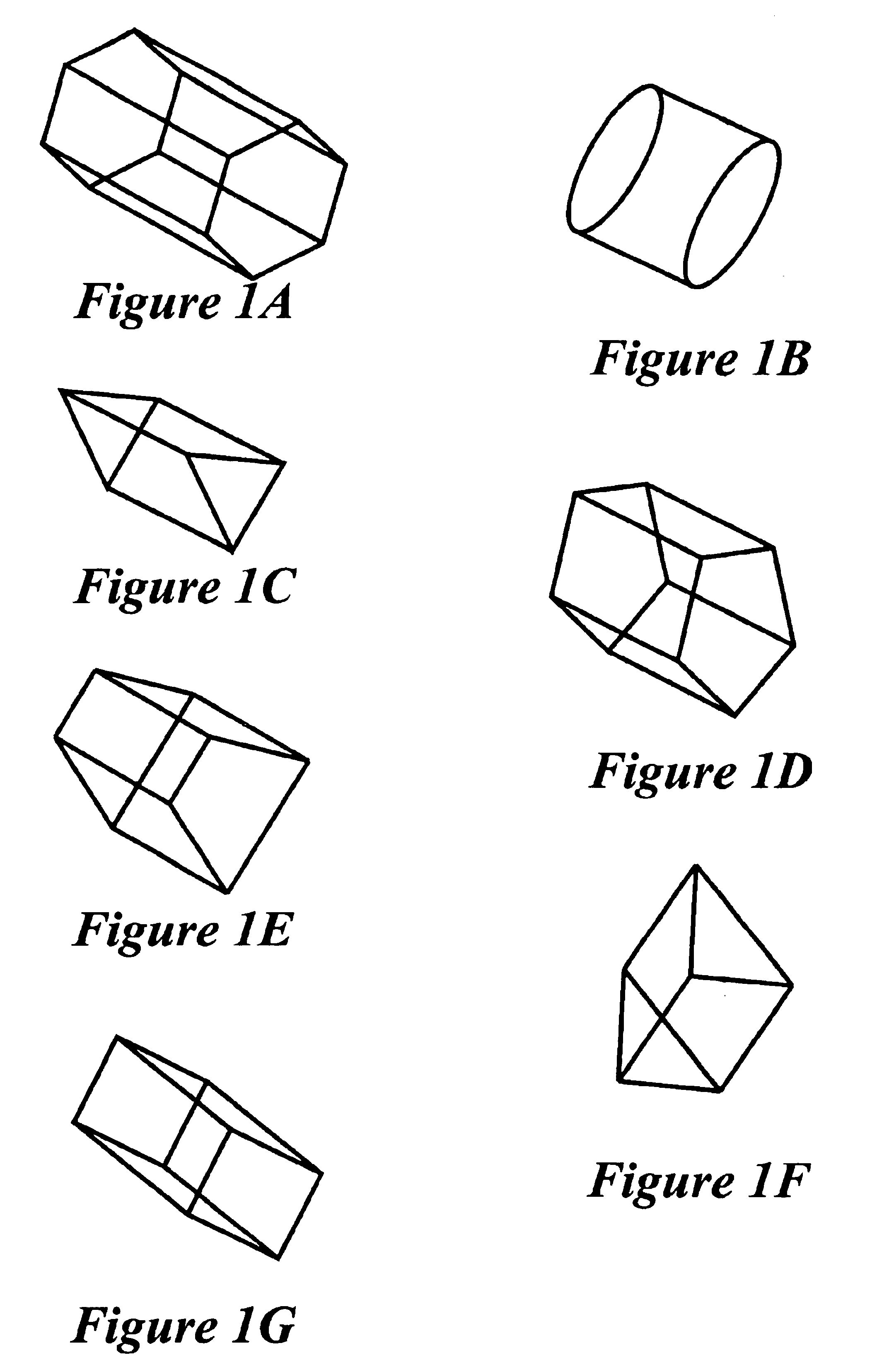
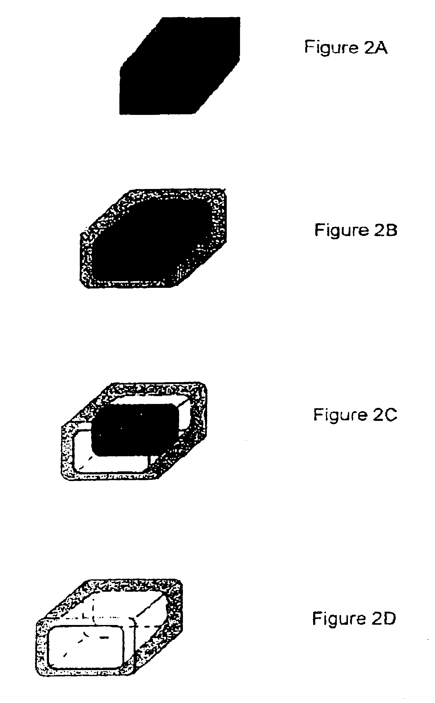
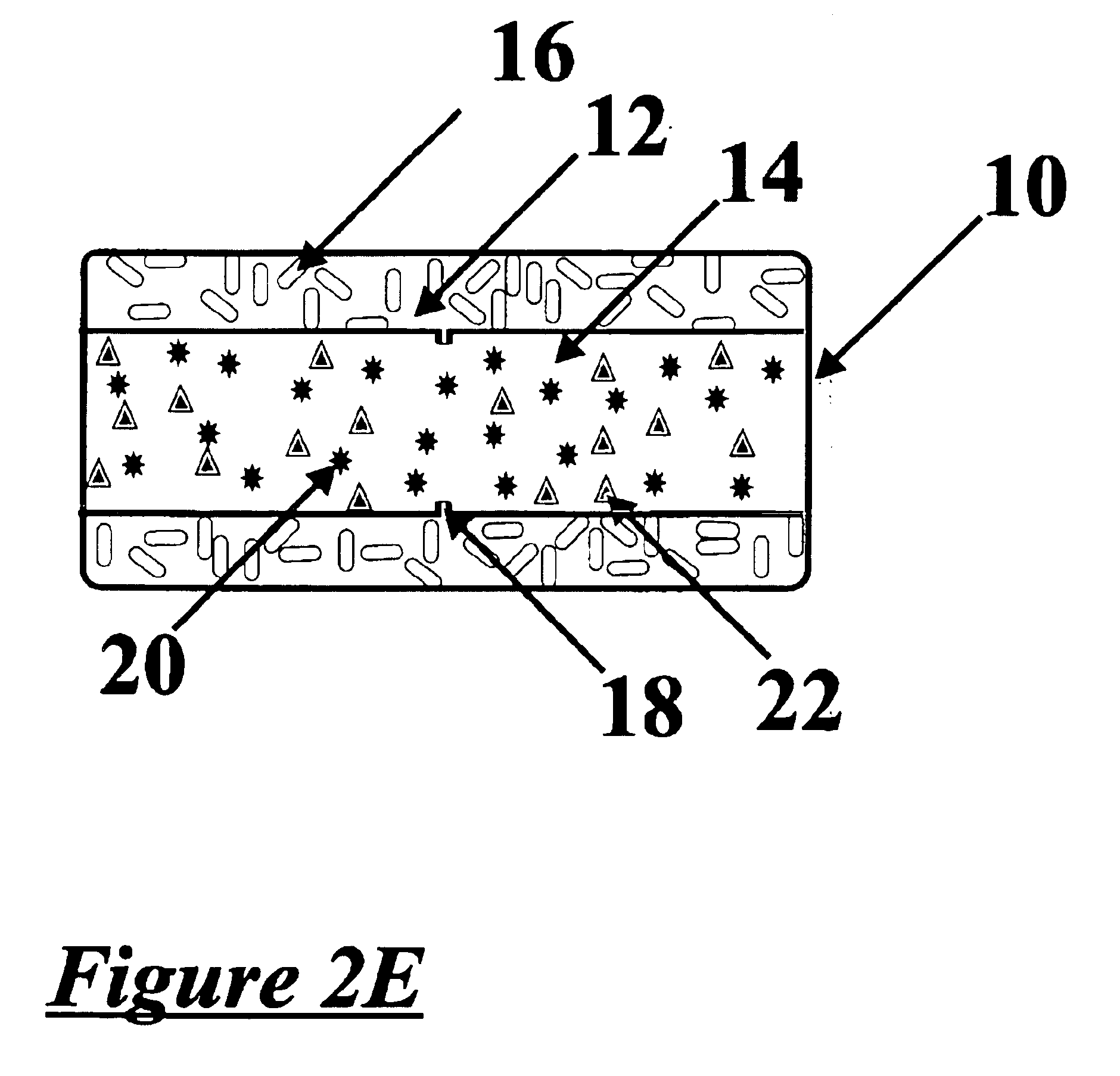
[0052]The delivery device of the present invention can be based on the dissolution mechanism. As shown in FIGS. 1A-G and 2A-E, the device preferably consists of a geometrically shaped core 10, preferably a rectangular, cubical or cylindrical shaped core. The core 10 contains a uniformly dispersed chemical compound or compounds including an active ingredient 20 and a dissolution regulator 22; preferably the uniformly dispersed active ingredients are therapeutically active compound(s). The compressed core can optionally be scored 18 to secure the slowly dissolving or disintegrating coating to the compressed core. A slowly dissolving or disintegrating coat 12 optionally containing pore-forming material 16 surrounds all but at least one face 14 of the core as shown in FIG. 2B. As the two exposed surfaces erode the two faces recede inwards until the core 10 is dissolved as shown in FIG. 2D. The chemical release occurs only from the exposed face(s) 14 whose surface area dictates the rate of release of chemical. Throughout the dissolution process, the surface area of the dissolution front is constant in these geometrical shapes and therefore the release substantially approximates zero-order kinetics. Because the exposed face(s) are in immediate contact with the fluid medium, the active ingredient is released immediately no lag time is observed. The volume of the core can be increased or decreased to accommodate different quantities of the active ingredient and excipients. The release rate, however, will be determined by the rate of erosion of the exposed surfaces and will be zero-order as long as the exposed surface of a dissolution device, or the ratio of the dissolution front to the diffusion path in a diffusion device, is constant. Another advantage of the present invention is the complete release of the active ingredient followed by the disintegration of remaining inert components of the delivery device. This is in contrast to many diffusion-based matrices, which leave a “ghost residue”.

Problems solved by technology

Standard tablets, however, generally disintegrate quickly and release all the active components over a relatively short period of time.
This is inconvenient and frequently leads to poorer patient compliance.
If the impermeable coating does not dissolve or disintegrate prior to passage through the gastrointestinal system, a “ghost” residue will remain which can be uncomfortable or undesirable to void.
Furthermore, passage of these residual coatings through the GI tract potentially can damage the intestinal mucosa.
However, such systems have not been completely successful usually either due to improper design of the system or due to a lack of appropriate and available manufacturing technology.
Swelling of the polymer, however, can deform the controlled release device and alter the release rates.
Attempts have been made to design dosage forms which produce variable release rates or pulsatile release but these have not been reliable or cost effective since they frequently possess complex architectures which are difficult to fabricate and are structurally weak.
Thus, the profile of the cavity ‘walls’ may be varied to provide pre-determined changes in the surface are so as to provide pulses of activity.” There is, however, no explanation of geometries which will produce nonlinear release nor does the geometry of the device allow for ready modification.
Existing devices have features that limit their applicability and practical production of effective controlled release agents has proven difficult.
Devices which do not provide for adequate quantities of a dissolution regulator have limited flexibility to optimize the delivery rate.
Water-soluble compounds will be released too rapidly when present in very high concentration in dissolution devices.
Devices which do not provide for insoluble modifiers are incapable of functioning as diffusion devices which are desirable when delivering hydrophobic compounds.
If improperly designed, the release rate from controlled release devices may vary over the release period.
Premature separation of the impermeable coating from the core can cause “dose dumping” as the uncoated core disintegrates Impermeable coatings in existing devices have no reliable disintegration mechanism which can lead to evacuation of the intact coating or release device.
Furthermore the amount of active substance which can be accommodated by these known devices is often limited by practical difficulties scaling the size and geometry of these architecturally complex devices.
The release rate from swellable cores also can be erratic due to the hydrodynamic conditions in the gastrointestinal tract as the swellable polymers are easily abraded.
A variety of geometrical designs have been suggested to overcome these problems; however, implementing these designs has often been problematical.

Method used


Image

  • Chemical delivery device
  • Chemical delivery device
  • Chemical delivery device

Examples


example 1

Dry Granulation Method for Core Compression

[0068]In an appropriate blender, the chemical is blended with a dissolution regulator which comprise the dissolution-based core. If required a soluble or insoluble diluent may also be added. Suitable polymers and diluents are known in the art and examples are described above. The blend may be milled and sieved, if desired, through a sieve with an appropriate size mesh, the mesh size is chosen according to the application. The blend is then mixed with a lubricant and the lubricated blend is compressed on a conventional rotary or single punch machine, examples of which are known in the art, into a tablet core of the appropriate shape and size.

example 2

Wet Granulation Method for Core Compression

[0069]In an appropriate blender, the chemical is blended with either a slow dissolving polymer—which comprise the shaped core. If required a soluble or insoluble diluent may also be added. The blend is subsequently granulated with water or an organic solvent or a mixture of water and an organic solvent. Alternatively a slow dissolving or dispersing polymer may be dissolved or dispersed in a solvent and added to the blend while mixing continuously. The mixture thus granulated is then dried at a suitable temperature and milled through a screen with an appropriate opening. The granules prepared are then mixed with a soluble or insoluble lubricant. The lubricated granules are compressed into a tablet core of the appropriate shape. Examples of suitable core compressing machines that may be used are known in the art and supplied by, for example Killian & Co. Inc. (Pennsylvania, USA), Thomas Engineering (Illinois, USA) and Fette America Inc. (New ...

example 3

Dry Granulation Method for Coating

[0070]An insoluble polymer and optionally a pore-former and / or a plasticizer are mixed in a suitable blender, and then the blend may be milled through a screen with an appropriate size mesh. The milled blend is lubricated with a soluble or insoluble lubricant. The core is covered with the blend and the coating applied by compression.


PUM

PropertyMeasurementUnit
Fractionaaaaaaaaaa
Timeaaaaaaaaaa

Abstract

The invention provides a controlled release dissolution and diffusion devices which can deliver an active ingredient at a constant or controlled-variable rate comprising an active ingredient and dissolution modifiers and / or an insoluble matrix. The compressed core is coated, except for at least one exposed face, with a coating containing an insoluble polymer or a mixture of an insoluble polymer and pore-forming elements said pore-forming elements having a dissolution rate slower that the release rate so that the pore formation is completed after release of the active ingredients and the residual inert structures disintegrate.

Description

REFERENCE TO PREVIOUS APPLICATIONS[0001]This application claims priority to U.S. Provisional Patent Application Ser. No. 60 / 293,701 filed May 25, 2001.FIELD OF THE INVENTION[0002]The present invention relates to controlled release chemical delivery devices, and more particularly to a controlled release drug delivery device, with a geometrically shaped body coated with a mixture of an insoluble polymer, optionally containing water-soluble pore-forming material(s) said pore-forming material(s) having a dissolution rate slower that the release rate so that the pore formation is completed after release of the active ingredients and the residual inert structures disintegrate.BACKGROUND OF THE INVENTION[0003]Effective drug therapy generally requires maintained drug levels in the blood stream for extended periods of time. Standard tablets, however, generally disintegrate quickly and release all the active components over a relatively short period of time. With these dosage forms drug level...

Claims


Application Information

Patent Timeline
IPC IPC(8): A61K9/28A61K9/20A61K9/22A61K9/30A61K9/32A61K9/36A61K31/4422A61K31/64A61K45/00A61K47/04A61K47/10A61K47/12A61K47/20A61K47/26A61K47/32A61K47/36A61K47/38A61K47/42
CPCA61K9/2086A61K9/2846A61K9/2866A61K9/2893
Inventor CHOPRA, SHAM
Owner MISTRAL PHARMA
Learn More