Cable support and distribution system and method

Inactive Publication Date: 2005-11-01
ERICO INT
View PDF26 Cites 40 Cited by
  • Summary
  • Abstract
  • Description
  • Claims
  • Application Information

AI Technical Summary

Benefits of technology

[0019]A cable support system provides the organization and support for bundles or runs of communication or datacom cables, for example, which avoids the common problems and mess usually associated with the distribution of data and communication cabling. The system is designed to be a low cost and easier to install cable tray, supporting runs or bundles of cable from a building structure such as a structural ceiling, beam, girder or purlin, and above a suspended acoustical ceiling. The system is suspended by common threaded rod from a wide variety of fasteners hanging the rod from the various structures. The rod supports a primary hanger which includes an upwardly opening generally rounded trough-shape support symmetrically below the rod with one side of the support extending integrally to the rod connection. The other side of the primary hanger is open so that a secondary hanger may be inserted and fastened to the inside of the upwardly opening support. This makes the entire cross section of the tray accessible from one side. The secondary hanger is preferably formed from rolls of flexible open plastic mesh having oriented strands. The length of the secondary hanger forms an upwardly opening trough supported by spaced primary hangers. The mesh is secured to the inside of the primary hangers by spring clips, and plastic splice clips may be used to join rolls of such mesh, or may be used in the fabrication of various transitions or branches. When the cable is in the trough formed by the secondary hanger, the open side of the hanger is closed by a connecting strap which also symmetrically transfers the load to both sides of the upwardly opening support or primary hanger. In addition to the five components noted, a sixth component in the form of a wire rod form transition fabrication may be employed to form curves, corners, Tees, or even changes in elevations. The transition comprises a center form support like the primary hanger but of wire rod form with a horizontal eye vertical axis hole formed at the top and a vertical eye horizontal axis hole at the opposite end. The eye at the top accommodates a threaded rod and the vertical eye accommodates the strap as with the primary hanger. A bottom center bendable strut or bar extends on each side of the center support, and upwardly extending trough-shape supports are mounted on the bendable strut on each side of the center support. The trough-shape supports at each end are paired and an end of the secondary hanger may be secured to said paired supports by the plastic splice clips described above. Intermediate trough-shape supports may be used to anchor the end of a secondary fastener in the formation of a Tee intersection.
[0020]The secondary mesh hanger may terminate at each end or may extend through the transition with a flap simply cut out at the Tee intersection. The system is inexpensive and may be installed above suspended ceilings without removing the grid or frame work.

Problems solved by technology

As the computer and communications industries have grown, the organization and management of the cabling has become a serious problem.
Cables such as UTP cables and fiber optic cables simply cannot be treated in such a cavalier fashion and have the equipment they serve meet expectations.
For example cross-talk on a telephone may be due to improper cabling or cable placement.
Attenuation, cross-talk, data distortion, and return loss all affect signal strength which can degrade any system transmission capability.
Background noise is also an irritating problem resulting from a low signal-to-noise ratio.
The wiring can be placed under the floor with elevated flooring which is extremely expensive and often not practical.
Conventional power wiring clips, snaps, wire hooks, bridle rings, or plastic ties are not suitable for such cable because of a variety of factors.
They may present sharp edges or produce sharp turns or kinks in the cabling, or they may crush or pinch a bundle.
Such trays are expensive and can be retrofitted into existing building, but not easily or economically, particularly if there is not a significant amount or extent of open or unobstructed horizontal space.
Flexibility and retrofitability are not particularly characteristic of these conventional cable tray systems.
These still are costly and require a number of parts, and cannot be retrofitted above an existing ceiling without substantially dismantling the ceiling.
They are more costly, more costly to install, and more costly to retrofit above an existing drop ceiling.
Both types share a similar disadvantage, in that the lengths provided are difficult to manage, and practically impossible to install over an existing drop ceiling without removing entire sections of the T-grid and cross brace system.
In addition, splices may require the installer to use several different tools to complete the splice, making them complicated and time-consuming to install.
This is hardly the type of tool which can be used easily, if at all, above a suspended ceiling without dismantling the whole ceiling.
This makes changes, additions, or transitions to the system more difficult.

Method used


Image

  • Cable support and distribution system and method
  • Cable support and distribution system and method
  • Cable support and distribution system and method

Examples


Embodiment Construction

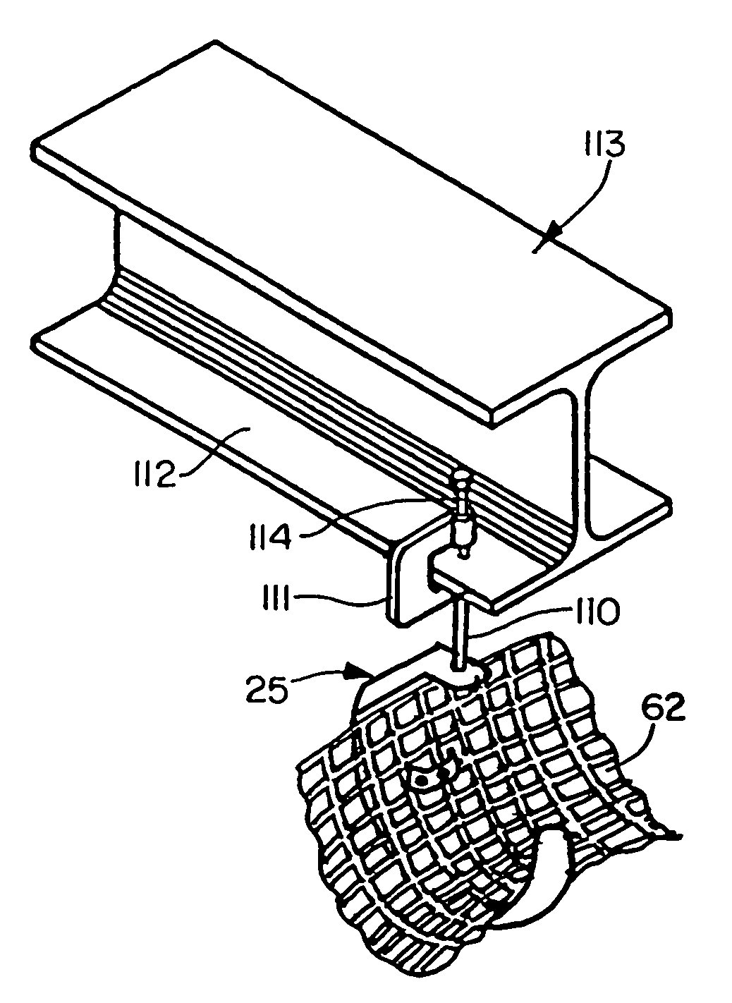
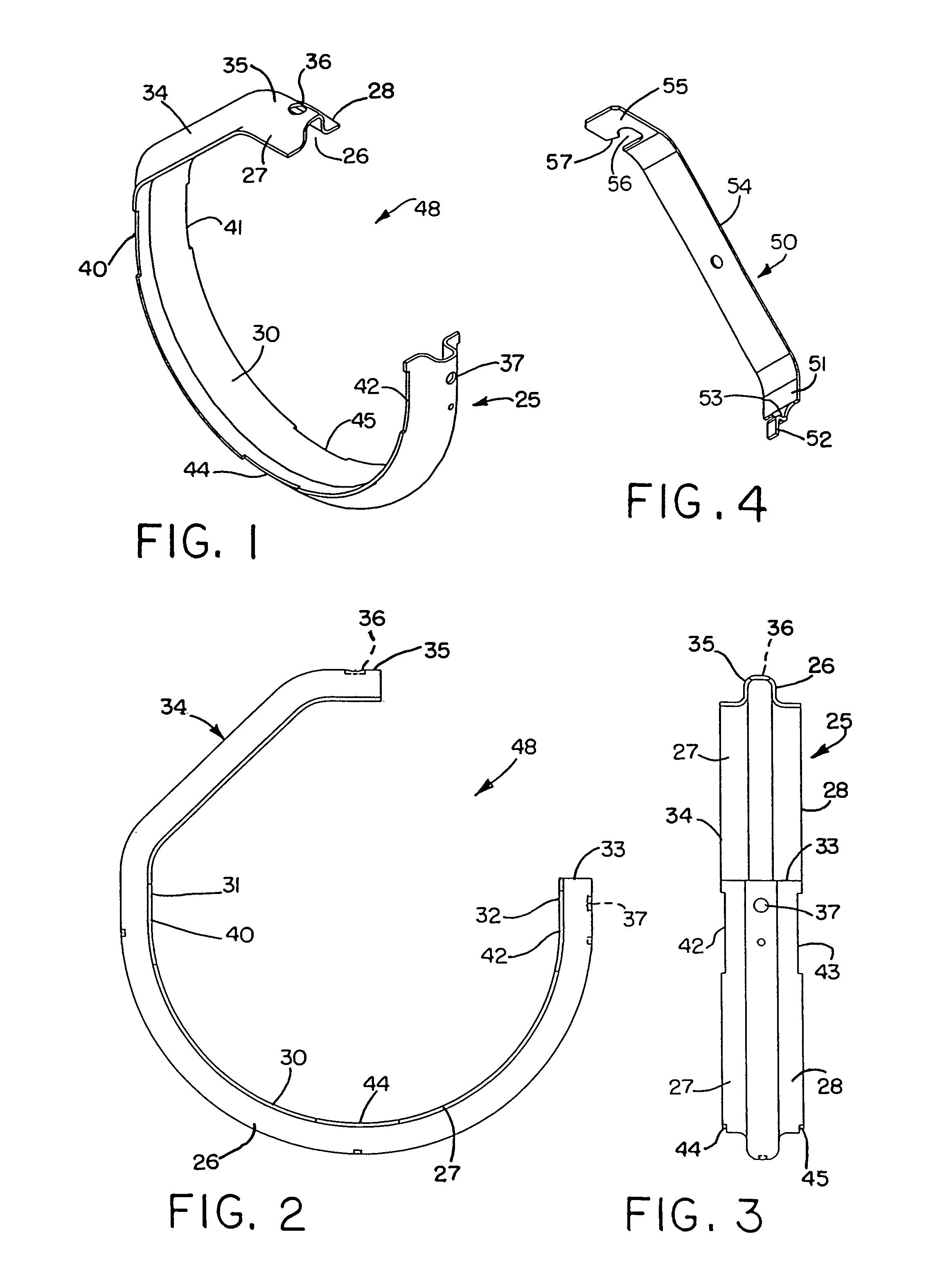
[0043]Referring initially to FIGS. 1–3 there is illustrated a primary hanger or bracket shown generally at 25. The hanger may be formed of steel and galvanized. Throughout its length, the hanger is of a substantially uniform channel shape which has a center outwardly extending channel 26 and two relatively long outwardly projecting coplanar flanges 27 and 28 on each side thereof. The bottom of the hanger forms a generally semi-circular upwardly opening trough-shape saddle or support 30 with two straight or vertical portions 31 and 32 on each end thereof. The straight portion 32 terminates at the edge 33 while the straight portion 31 continues upwardly to an angle portion 34 which terminates at the top in a horizontal short section 35. The base of the channel is provided with a top hole indicated at 36.

[0044]The opposite end just short of the edge 33 is also provided with a hole seen at 37 in the base at the center channel. As later described, the primary hanger or bracket may be hun...


PUM


Abstract

A cable support system provides the organization and support for bundles or runs of communication or database cables, for example, avoiding the mess usually associated with the distribution of such cabling. The system is designed to be a low cost and easier to install tray, supporting runs or bundles of cable from a building structure such as a structural ceiling, beam, girder, or purlin, and above a suspended acoustical ceiling. The system is suspended by common threaded rod which supports a primary hanger having a generally rounded support symmetrically below the rod with one side openable so that a secondary hanger may be inserted in and fastened to the inside of the support. The secondary hanger is formed from a roll of flexible open plastic mesh having oriented strands secured to the inside of the primary hangers by spring clips. Plastic splice clips may be used to join lengths of such mesh, or may be used in the fabrication of various transitions or branches. A wire form transition to which the secondary hanger is secured by the splice clips includes bendable components and can be used to form curves, elbows, changes in elevation, or Tees, and the like.

Description

[0001]This application is a continuation of a Provisional Application Ser. No. 60 / 145,322, filed Jul. 23, 1999.[0002]This invention relates generally as indicated to a cable support and distribution system and method, and more particularly to a low cost support and distribution system for interior runs of telecommunications and like cable which is of simplified construction, and which can easily be installed, and more particularly retrofitted, above existing acoustical or grid ceilings, with the removal of only a few grid tiles. The invention also relates to a method of supporting and organizing such cable.BACKGROUND OF THE INVENTION[0003]UTP category 5 cable is a data or communications cable constructed of 4 unshielded twisted pairs of 24 AWG thermoplastic insulated conductors enclosed is a thermoplastic jacket. The pairs of copper wires are tightly twisted to achieve high speed transmission; the tighter the twist, the faster the possible transmission speed. While UTP is available ...

Claims


Application Information

Patent Timeline
IPC IPC(8): F16L3/06F16L3/02F16L3/26H02G3/04H02G3/30
CPCF16L3/26H02G3/0456H02G3/30
Inventor LAUGHLIN, RAYMOND S.DIFRANCISCO, JOHN A.LYNCH, JR., EDWARD J.
Owner ERICO INT
Why Eureka
Try Eureka