Press brake and ram movement method for press brake

a technology of press brake and ram, which is applied in the direction of presses, manufacturing tools, etc., can solve the problems of increased man-hours, increased risk, and increased risk of oil leakage of piping 211, so as to reduce shock, increase ram speed, and improve productivity

Inactive Publication Date: 2005-11-01
AMADA CO LTD
View PDF12 Cites 11 Cited by
  • Summary
  • Abstract
  • Description
  • Claims
  • Application Information

AI Technical Summary

Benefits of technology

[0022]Therefore, according to the present invention, since it is not necessary to employ the conventional switch valve, and it is not necessary to rotate the two-way piston pump in a state of stopping the hydraulic cylinder, it is possible to prevent an oil temperature from being increased. Accompanying with this, it is possible to widely reduce the capacity of the oil tank, and it is possible to intend to make the apparatus compact.
[0036]Therefore, according to the present invention, it is not necessary to employ the conventional switch valve. Accordingly, since it is possible to reduce the shock at a time of depressure and it is possible to increase the ram speed at a time of depressure, it is possible to improve the productivity. Further, since no switch valve is provided, it is possible to prevent the conventional vibration from being generated by the switch valve. Further, since a flow rate property is not affected by the pressure, a motion gain of the ram is not changed so much, so that it is possible to prevent the vibration due to the change of the flow rate property against the pressure.

Problems solved by technology

That is, since it is necessary to assemble the hydraulic cylinders 207L and 207R with the hydraulic equipment 209 according to an independent setup, and pipe them after mounting to a predetermined position, there is a problem that not only an operation man hour is increased, but also a risk is involved.
Further, since a long piping 211 is provided, there is a problem that the piping 211 is in danger of oil leak.
Further, since a distance between the control valve provided in the hydraulic equipment 209 and the hydraulic cylinders 207L and 207R is long, a response is bad, a pressure loss is great and a heat generation is accompanied, so that there is a problem that a controllability is bad.
Further, a working fluid in the oil tank is sucked into the hydraulic cylinders 207L and 207R by utilizing its own weight of the upper table 205U at a time of rapidly dropping, however, a temperature of the working fluid is low at a time of starting the process and a viscosity thereof is high, whereby a sufficient speed can not be obtained due to generation of suction lack or a cavitation is generated, so that there is a problem of a risk that a performance decrement is involved.
Further, a temperature of a frame is increased due to the heat generation, a heat deformation is generated in the frame, and a reduction of bending work accuracy is caused.
Accordingly, there is a problem that an actuator having a great capacity is required for moving the switch valve 311, whereby a cost increase is caused and the switch valve 311 is enlarged.
Further, there is a case that the switch valve 311 vibrates due to a strong external force at a time of discharging the working fluid at a high pressure, and there is a risk that a vibration is generated in the upper table 301U corresponding to the ram.
Further, as shown in FIG. 4, since a “opening degree−flow rate” property of the switch valve 311 is different between an unload time (a low pressure time) and a load time (a high pressure time), there is a risk that a motion gain of the ram is changed so as to generate the vibration.
Accordingly, since the structure is made such as to make a ram speed at a time of depressure slow so as to reduce generation of the vibration, there is a problem that a productivity is deteriorated.

Method used


Image

  • Press brake and ram movement method for press brake
  • Press brake and ram movement method for press brake
  • Press brake and ram movement method for press brake

Examples


Embodiment Construction

[0048]A description will be in detail given below of an embodiment according to this invention with reference to the accompanying drawings.

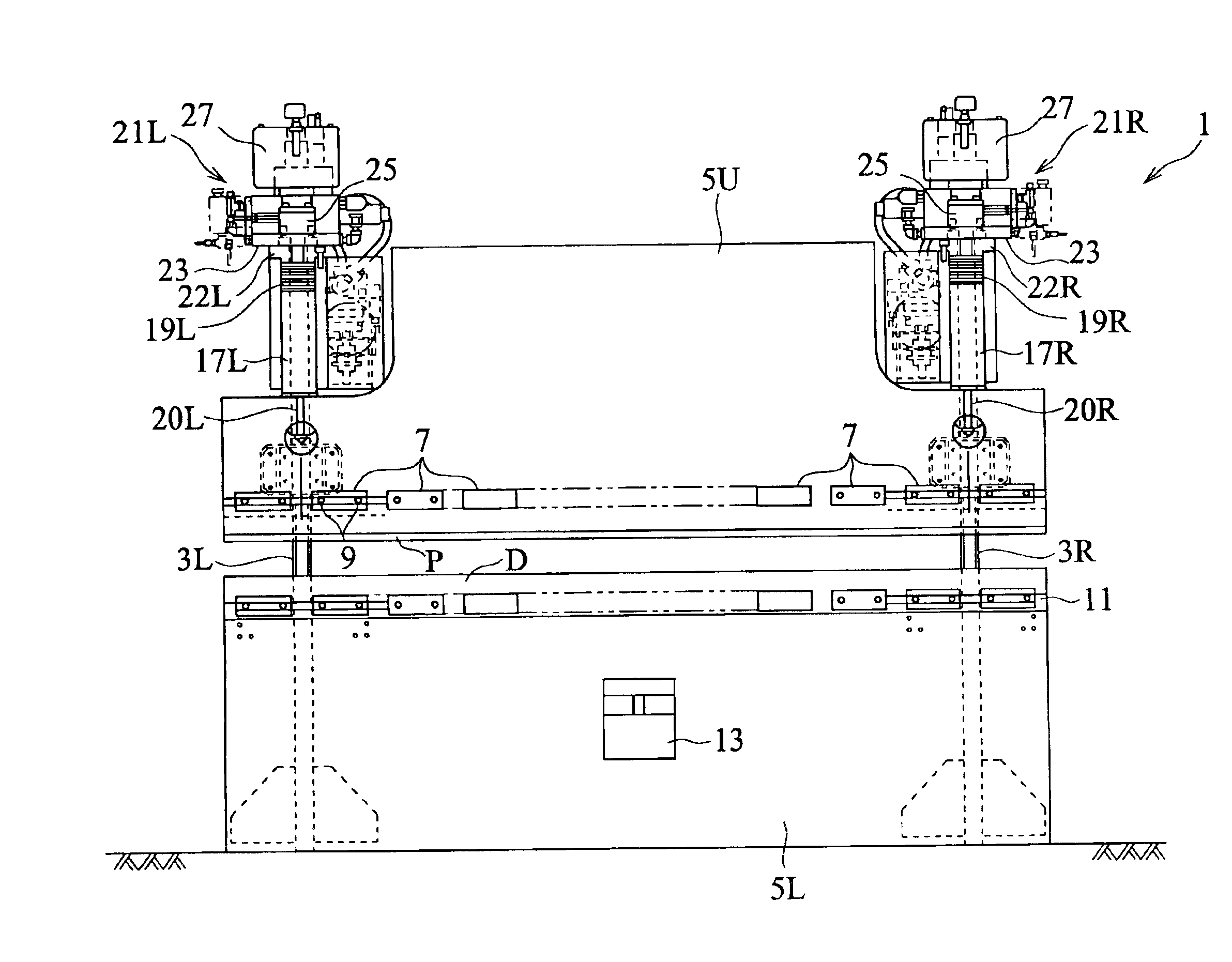
[0049]In FIGS. 5 and 6, there is shown a whole of a press brake 1 according to this invention. This press brake 1 has side plates 3L and 3R provided so as to be stood in left and right sides, is provided with an upper table 5U serving as a first table on front end surfaces of upper portions in the side plates 3L and 3R so as to freely move upward and downward, and is provided with a lower table 5L serving as a second table on front surfaces of lower portions in the side plates 3L and 3R.

[0050]A punch P is provided in a lower end portion of the upper table 5U by a bolt 9 via an intermediate plate 7 so as to be freely replaced. Further, a die D is provided in an upper end portion of the lower table 5L via a die base 11 so as to be freely replaced.

[0051]Both end portions of the lower table 5L are fixed to the side plates 3L and 3R, however, a center...


PUM

PropertyMeasurementUnit
pressure lossaaaaaaaaaa
temperatureaaaaaaaaaa
viscosityaaaaaaaaaa

Abstract

In a press brake relatively moving an upper table (5U) or a lower table (5L) upward and downward by a plurality of hydraulic cylinders (17L and 17R) so as to perform a bending work, the respective hydraulic cylinders (17L, 17R) are driven by individually controlling a pair of left and right two-way. fluid pumps and hydraulic devices (21L, 21R) provided in correspondence to the respective hydraulic cylinders (17L, 17R) The two-way fluid pumps and the respective hydraulic devices (21L, 21R) are mounted to a base plate (23) mounted to cylinder heads (18L, 18R) of the respective hydraulic cylinders (17L, 17R), and an oil tank (27) is provided in an upper side of the hydraulic devices (21L, 21R).

Description

TECHNICAL FIELD[0001]This invention relates to a press brake provided with a hydraulic cylinder for moving an upper table or a lower table relatively to each other upward and downward, and a ram moving method in a press brake for performing a bending work by relatively moving an upper table or a lower table upward and downward.BACKGROUND ART[0002]With reference to FIGS. 1 and 2, a conventionally general hydraulic press brake 201 has side plates 203L and 203R provided in a standing manner left and right, has an upper table 205U on upper front end surfaces of the side plates 203L and 203R so as to freely move upward and downward, and is provided with a lower table 205L on lower front surfaces of the side plates 203L and 203R in a fixed manner.[0003]Further, hydraulic cylinders 207L and 207R for moving the upper table 205U upward and downward are provided in the upper front surfaces of the side plates 203L and 203R, and a hydraulic equipment 209 such as a pump, an oil tank, a control v...

Claims


Application Information

Patent Timeline
Patent Type & Authority Patents(United States)
IPC IPC(8): B21D5/02
CPCB21D5/02
Inventor KANNO, KAZUHIRO
Owner AMADA CO LTD
Why Eureka
Try Eureka