
Permanent downhole, wireless, two-way telemetry backbone using redundant repeaters

a two-way telemetry and repeater technology, applied in the field of permanent downhole, wireless, two-way telemetry backbone using redundant repeaters, can solve the problems of bellows-type gas-lift valve, excessive kick off pressure, rare in practice,

Inactive Publication Date: 2005-10-25
SHELL OIL CO
View PDF6 Cites 245 Cited by
  • Summary
  • Abstract
  • Description
  • Claims
  • Application Information

AI Technical Summary

Benefits of technology

The present invention provides a system and method for communicating among devices in a well using a piping structure and an induction choke. The system includes a piping structure with a conductive portion, a first communication device, a second communication device, and an induction choke. The first and second devices are connected to the conductive portion of the piping structure and can communicate with each other using time-varying current signals. The system can also include a computer system and a downhole device for data communication. The technical effects of the invention include improved communication among devices in a well, increased efficiency of signal transmission, and improved data processing.

Problems solved by technology

Although the tubing can be used for the injection of the lift-gas and the annular space used to produce the oil, this is rare in practice.
Initially, the gas-lift wells simply injected the gas at the bottom of the tubing, but with deep wells this requires excessively high kick off pressures.
Several problems are common with bellows-type gas-lift valves.
First, the bellows often loses its pre-charge, causing the valve to fail in the closed position or changing its setpoint to operate at other than the design goal, and exposure to overpressure causes similar problems.
Another common failure is erosion around valve seat 319 and deterioration of the ball stem in the valve.
This leads to partial failure of the valve or at least inefficient production.
Because the gas flow through a gas-lift valve is often not continuous at a steady state, but rather exhibits a certain amount of hammer and chatter as ball 318 rapidly opens and closes, ball and valve seat degradation are common, leading to valve leakage.
Failure or inefficient operation of bellows-type valves leads to corresponding inefficiencies in operation of a typical gas-lift well.
Fundamentally these difficulties are caused by the present inability to monitor, control, or prevent instabilities, since the valve characteristics are set at design time, and even without failure they cannot be easily changed after the valve is installed in the well.
It is often highly undesirable and in practice difficult to use a cable along the tubing string either integral with the tubing string or spaced in the annulus between the tubing and the casing because of the number of failure mechanisms present in such a system.
But such standard electrical conduits can be difficult to route at great depths, around turns for deviated wells, along multiple branches for a well having multiple lateral branches, and / or in parallel with coil production tubing.
Therefore, the method and system described in U.S. Pat. No. 4,839,644 is expensive, has problems with brine leakage into the casing, and is difficult to use for downhole two-way communication.
Other downhole communication concepts, such as mud pulse telemetry (U.S. Pat. Nos. 4,648,471 and 5,887,657), have shown successful communication at low data rates but are of limited usefulness as a communication scheme where high data rates are required or it is undesirable to have complex, mud pulse telemetry equipment downhole.
Surface indications of production conditions are useful, but feedback to determine optimum production of the well can take many hours and even days.

Method used


Image

  • Permanent downhole, wireless, two-way telemetry backbone using redundant repeaters
  • Permanent downhole, wireless, two-way telemetry backbone using redundant repeaters
  • Permanent downhole, wireless, two-way telemetry backbone using redundant repeaters

Examples


first embodiment

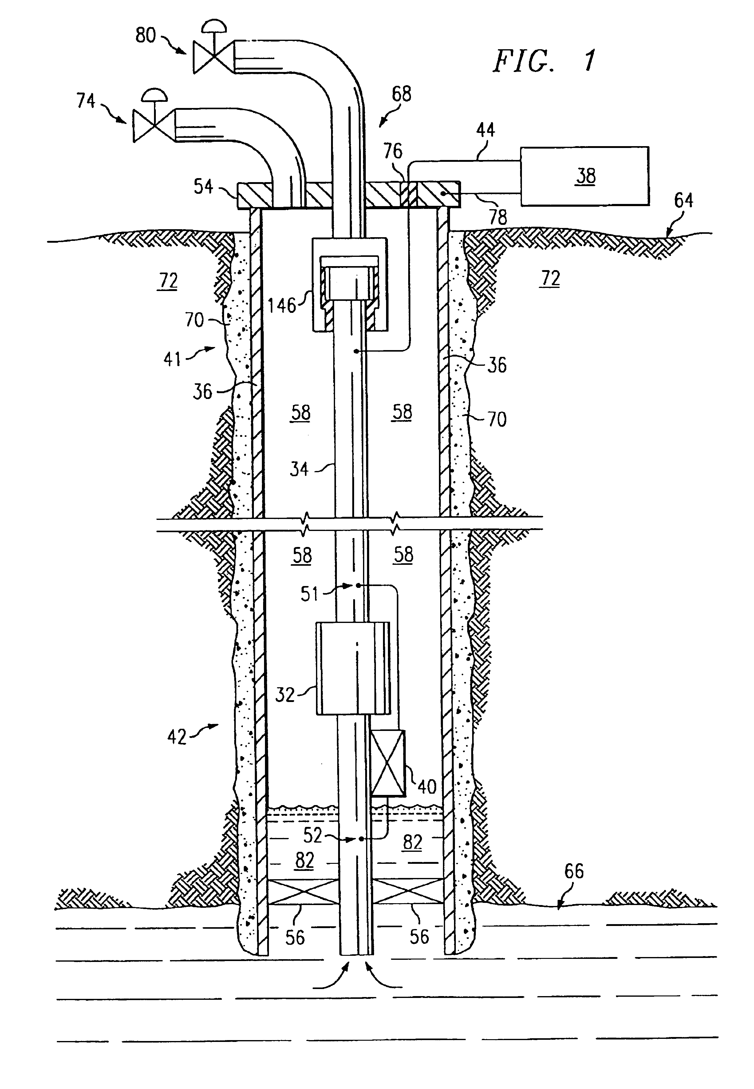
[0049]In the first embodiment shown in FIG. 1, the piping structure comprises a production tubing string 34 for a well, which is typically steel tubing. The system has an electrical impeding device 146 located about the tubing 34 along a first end 41 near the surface. Device 146 may consist of an electrically insulating joint as shown in FIG. 1, or an unpowered choke of the present invention. A lower choke 32 is located about the tubing along a second end 42 downhole within the well. Surface equipment 38 comprises a power source to energize downhole equipment, and a computer-controlled modem to send and receive commands and data to downhole equipment. Power and communications signals are output from surface equipment 38 as time-varying currents and are electrically connected to the tubing 34 between the impeding devices 146, 32 using connectors 44 and 78. The time-varying current can be alternating current (AC) or a varying direct current (DC), but AC is typically more practical in ...

third embodiment

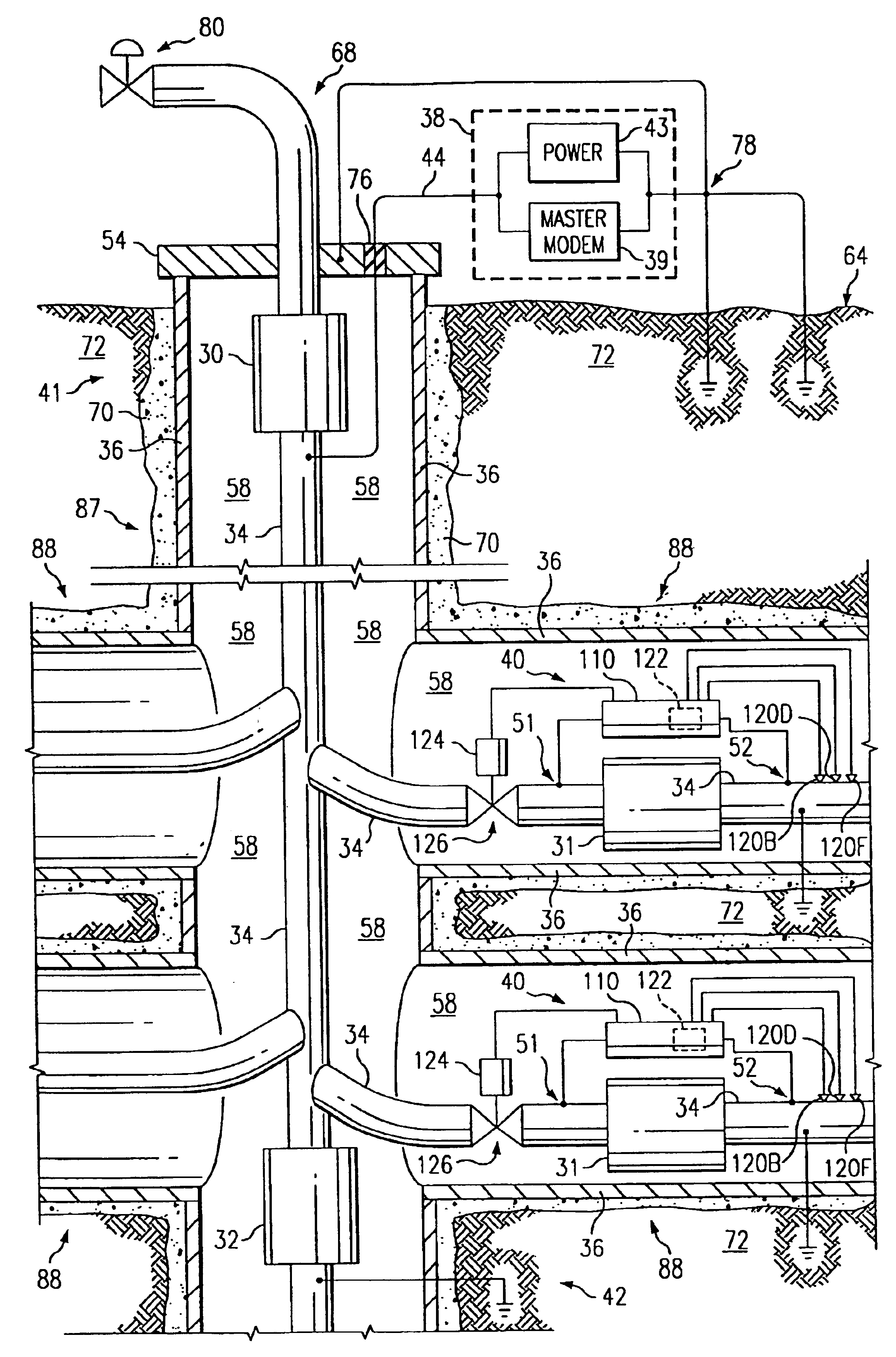
[0115]Other types of configurations are contemplated. For example, FIG. 9 shows a multilateral petroleum well application of a third embodiment in accordance with the present invention. In a multilateral completion shown in FIG. 9, the tubing 34 is used as a conductor for power and communication signals, and the earthen ground is used as an electrical return. A controllable valve 126, a downhole spread spectrum modem 122, and sensors 120 are placed in each lateral. The main borehole 87 branches into four laterals 88. The source 38 comprises a computer system having an AC power supply 43 and a master modem 39. As long as a time-varying current is output to the electrical circuit, the source 38 may comprise any variety of electronic components, including but not limited to: a computer system, a modem, a power supply, a software program for analyzing data, a software program for controlling downhole devices, or any combination thereof. Redundant relay modems (not shown) can be included...


PUM


Abstract

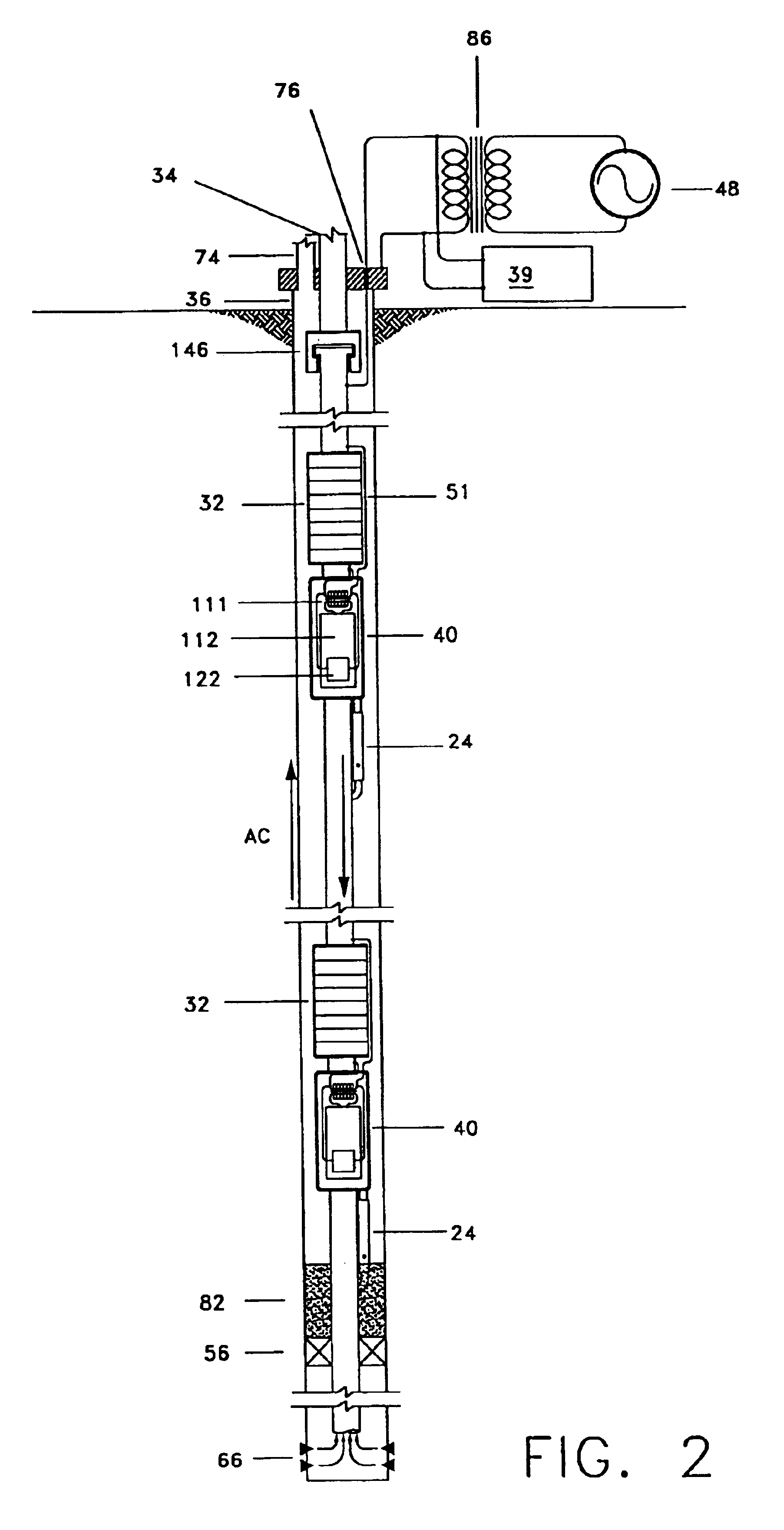
A system and method of communicating among devices via a piping structure using at least one induction choke about the piping structure to route a time-varying current carrying communication signals between the devices. A communications system comprises a piping structure, a first communication device, a second communication device, and an induction choke. The piping structure comprises a first location, a second location, and an electrically conductive portion extending between the first and second locations. The first and second locations are distally spaced along the piping structure. The first and second communication devices are each electrically connected to the electrically conductive portion of the piping structure along the first location and second location, respectively, and each is adapted to send and receive communication signals via time-varying current. The induction choke is located about an electrically choked portion of the electrically conductive portion of the piping structure, such that the induction choke is adapted to route time-varying current within the piping structure between the electrical connection location for the first communication device and the electrical connection location for the second communication device, and such that the first communication device can communicate with the second communication device via the piping structure. A preferred application of the present invention is a well for producing petroleum products (e.g., oil, natural gas), comprising a communication system as described above.

Description

CROSS-REFERENCES TO RELATED APPLICATIONS[0001]This is a division of application Ser. No. 09 / 768,655 filed Jan. 24, 2001, the entire disclosure of which is hereby incorporated by reference[0002]This application claims the benefit of the U.S. Provisional Applications in the following table, all of which are hereby incorporated by reference:[0003]U.S. PROVISIONAL APPLICATIONST&K #Ser. No.TitleFiling DateTH 159960 / 177,999Toroidal Choke Inductor forJan. 24, 2000Wireless Communication andControlTH 1599x60 / 186,376Toroidal Choke Inductor forMar. 2, 2000Wireless Communication andControlTH 160060 / 178,000Ferromagnetic Choke inJan. 24, 2000WellheadTH 1600x60 / 186,380Ferromagnetic Choke inMar. 2, 2000WellheadTH 160160 / 186,505Reservoir ProductionMar. 2, 2000Control from IntelligentWell DataTH 160260 / 178,001Controllable Gas-Lift WellJan. 24, 2000and ValveTH 160360 / 177,883Permanent, Downhole,Jan. 24, 2000Wireless, Two-WayTelemetry Backbone UsingRedundant Repeater, SpreadSpectrum ArraysTH 166860 / 177,...

Claims


Application Information

Patent Timeline
Patent Type & Authority Patents(United States)
IPC IPC(8): E21B47/10E21B17/00E21B34/06E21B34/00E21B34/16E21B33/129E21B17/02E21B47/12E21B43/00E21B37/06E21B37/00E21B41/02E21B33/12E21B34/08E21B41/00E21B47/06E21B43/12E21B43/14E21B43/16H04B13/00H04B13/02H04B5/00
CPCE21B43/122E21B47/12E21B17/003E21B17/028E21B33/1294E21B34/066E21B34/08E21B34/16E21B37/06E21B41/0085E21B41/02E21B43/12E21B43/123E21B43/14E21B43/16E21B47/06E21B47/10E21B47/1005E21B47/101E21B47/1015E21B47/122H04B13/02E21B2041/0028E21B2200/22E21B47/103E21B47/107E21B47/13E21B47/11E21B17/0285E21B43/1235E21B17/0283
Inventor VINEGAR, HAROLD J.BURNETT, ROBERT REXSAVAGE, WILLIAM MOUNTJOYCARL, JR., FREDERICK GORDONHALL, JAMES WILLIAMHIRSCH, JOHN MICHELE
Owner SHELL OIL CO
Learn More