Coaxial connector with center conductor seizure
a center conductor and coaxial connector technology, applied in the direction of connections, basic electric elements, electric devices, etc., can solve the problems of high installation burden, complexity of such connectors, and relatively high parts coun
- Summary
- Abstract
- Description
- Claims
- Application Information
AI Technical Summary
Benefits of technology
Problems solved by technology
Method used
Image
Examples
second embodiment
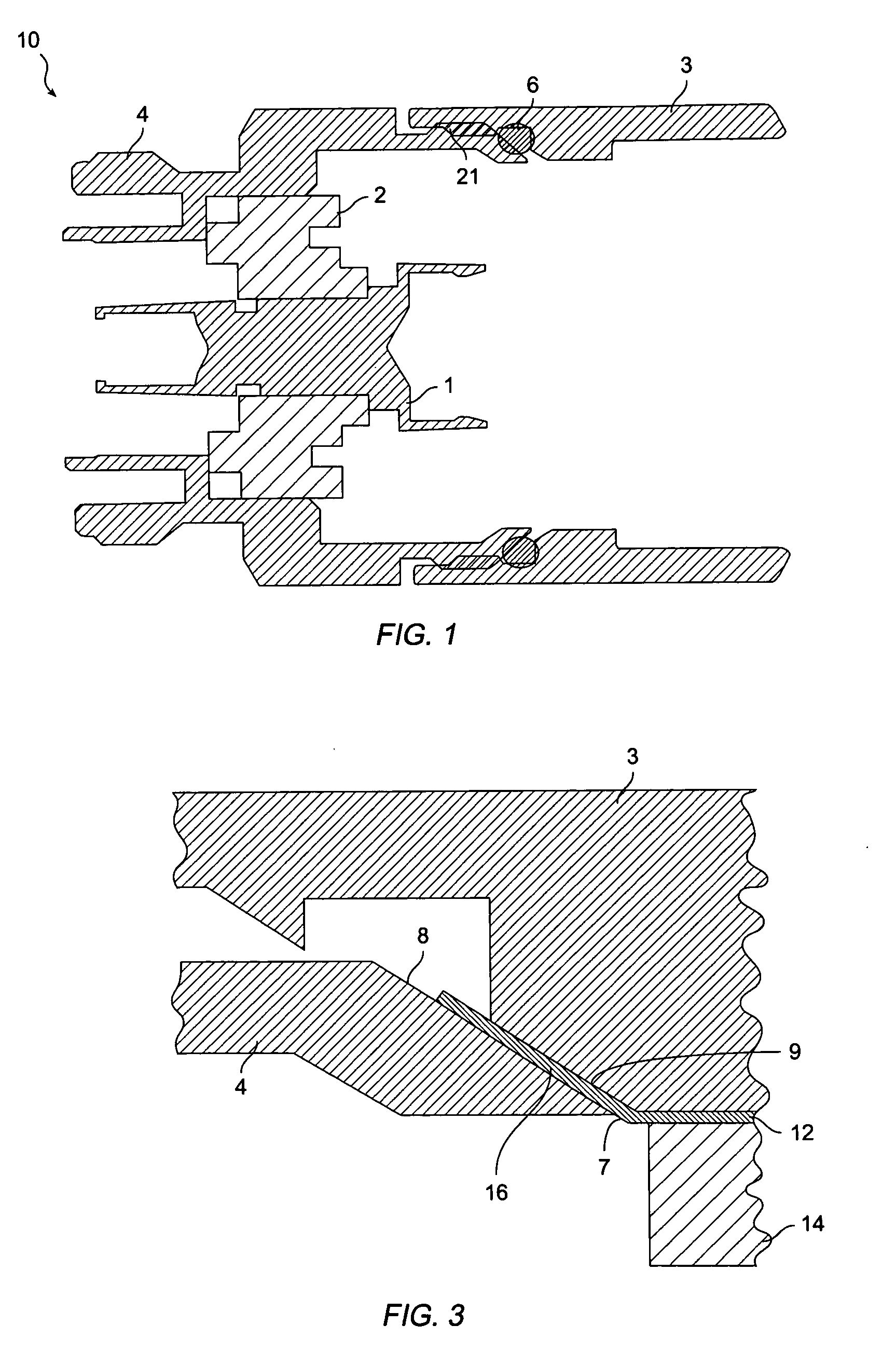
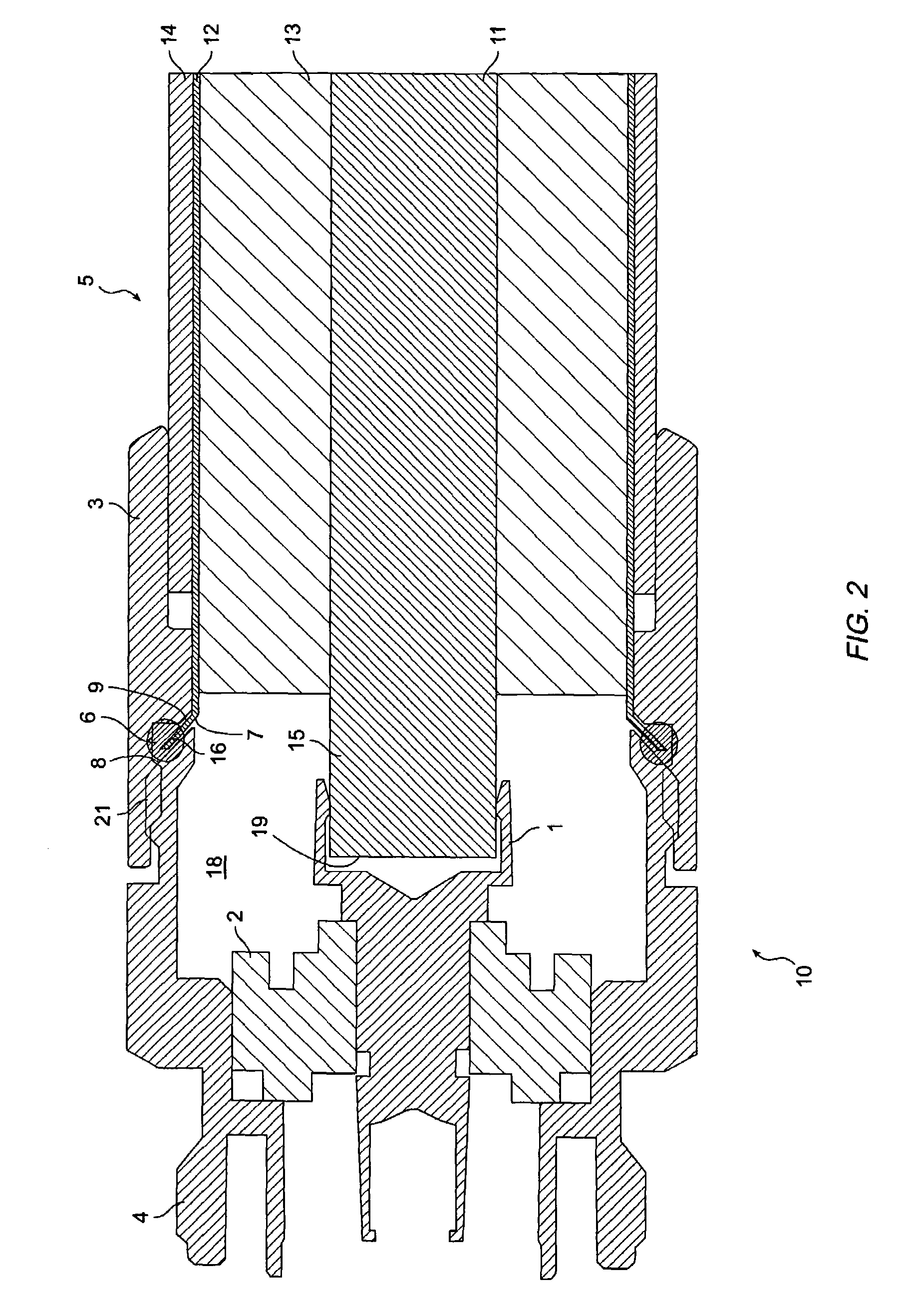
[0043] the coaxial cable may be mounted to coaxial connector 10 without removing either jacket 14 or dielectric 13. The steps for mounting the cable to coaxial connector 10 according to this method, are as follows: first, an end portion of the cable is inserted through back nut 3. A tool is then used to pry the end portion of outer conductor 12 away from dielectric 13, and to flare the end of outer conductor 12 outwardly, as mentioned above. The inner conductor of the coaxial cable is then inserted into inner terminal 1 of the connector as described above, and back nut 3 is screwed over outer terminal 4 until there is a mechanical stop, leaving the end portion of the cable securely clamped between faces 8, and 9 of the outer terminal 4 and back nut 3. The cable can be mounted according to this method as long as there is a sufficient contact between the outer conductor portion 7 and face 8 of outer terminal 4.
third embodiment
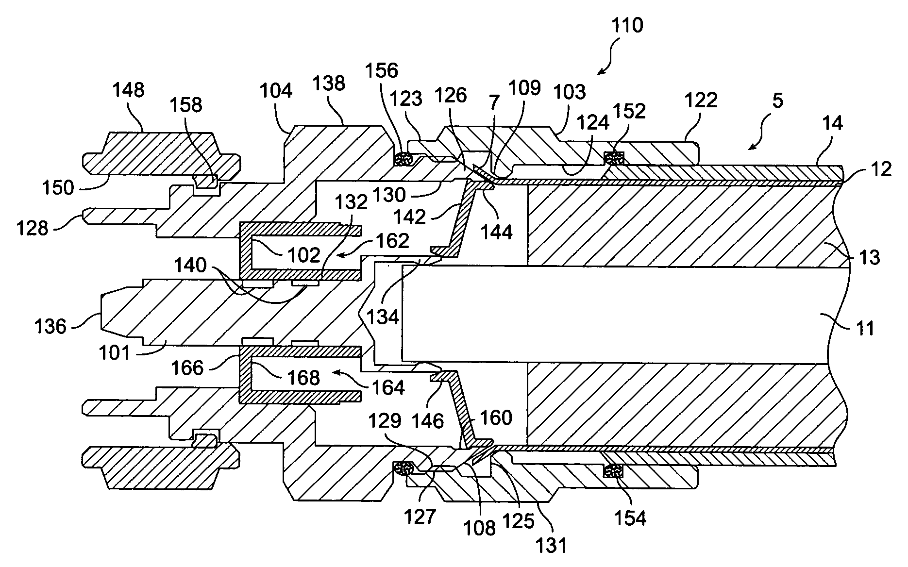
[0044] the cable is mounted by removing the dielectric within the exposed end of the coaxial cable, but not the cable jacket. This is a combination of the two previous embodiments. The steps for mounting the cable are as follows: first, a sufficient amount of dielectric material 13 is removed from the end portion of cable 5. The exposed end of coaxial cable 5 is then inserted through the central aperture of back nut 3. The end portion 7 of outer conductor 12 is again flared outwardly. The inner conductor 15 of coaxial cable 5 is then inserted into inner terminal 1 of connector 10, as described above. The back nut 3 is then longitudinally displaced, as by screwing back nut 3 onto outer terminal 4, so that the flared outer conductor and adjoined insulating jacket are clamped securely between the outer terminal's contact face 8 and the abutting back nut face 9.
[0045]Turning to FIG. 4, a coring tool and cooperating collar are shown for removing foam dielectric from between the inner con...
PUM
 Abstract
Description
Claims
Application Information
 - R&D
- Intellectual Property
- Life Sciences
- Materials
- Tech Scout
- Unparalleled Data Quality
- Higher Quality Content
- 60% Fewer Hallucinations
Browse by: Latest US Patents, China's latest patents, Technical Efficacy Thesaurus, Application Domain, Technology Topic, Popular Technical Reports.
© 2025 PatSnap. All rights reserved.Legal|Privacy policy|Modern Slavery Act Transparency Statement|Sitemap|About US| Contact US: help@patsnap.com


