
Insulated concrete cast panels with voids in billits

Inactive Publication Date: 2005-10-18
FABCON
View PDF21 Cites 24 Cited by
  • Summary
  • Abstract
  • Description
  • Claims
  • Application Information

AI Technical Summary

Benefits of technology

[0008]The invention provides all of the benefits of hollow core concrete panels with the advantages of insulating foam billets in the hollow core regions. This eliminates the need to use core material to form the hollow cores. In addition, extruders to extrude in the core material are no longer required. Since the extruders may be eliminated, it is also now possible with the invention to cast openings into the panels by placing forms to limit where the concrete flows. The use of core material necessitates additional handling difficulties, including lifting and tilting the panels to remove the core material, as best shown in U.S. Pat. No. 4,398,761, the disclosure of which is incorporated herein by reference. Even with the extra steps of forming lifting inserts, and having cranes to lift and tilt the panels, about a ton of core material is left in each panel, adding undesired weight and cost.
[0009]This improvement consists in using foam billets that form a hollow channel from end to end such that electrical conduit or other utilities may be readily run through the finished product without having to cut or otherwise form an opening through the length of the panel.
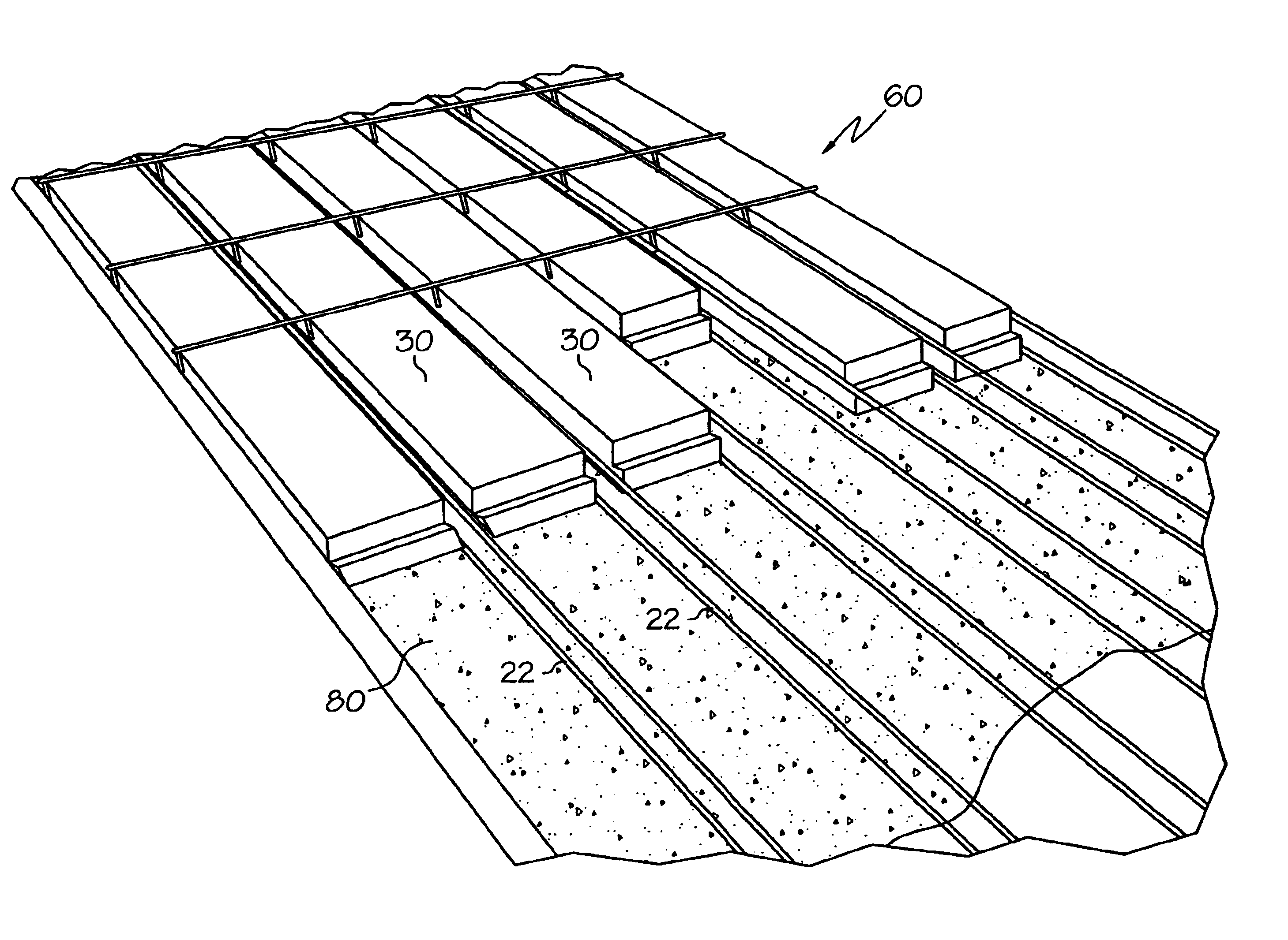
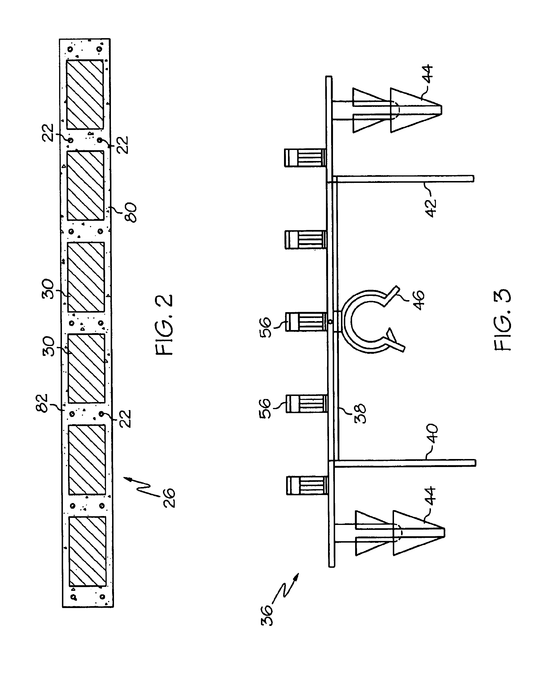
[0010]The generally rectangular-shaped foam billets are held together with raft connectors into a “raft” of foam billets. The unique raft connectors allows the foam billets to be connected together after each billet is placed on the bed. Alternatively, an entire raft of billets may be placed on the bed after being pre-assembled. The finished panel and plank is only “hollow core” in that cores of foam and defined open channels are formed throughout the panels and planks which provides insulation, requires far less concrete and eliminates a great deal of weight per panel or plank.

Problems solved by technology

The use of core material necessitates additional handling difficulties, including lifting and tilting the panels to remove the core material, as best shown in U.S. Pat. No. 4,398,761, the disclosure of which is incorporated herein by reference.
Even with the extra steps of forming lifting inserts, and having cranes to lift and tilt the panels, about a ton of core material is left in each panel, adding undesired weight and cost.

Method used


Image

  • Insulated concrete cast panels with voids in billits
  • Insulated concrete cast panels with voids in billits
  • Insulated concrete cast panels with voids in billits

Examples


Embodiment Construction

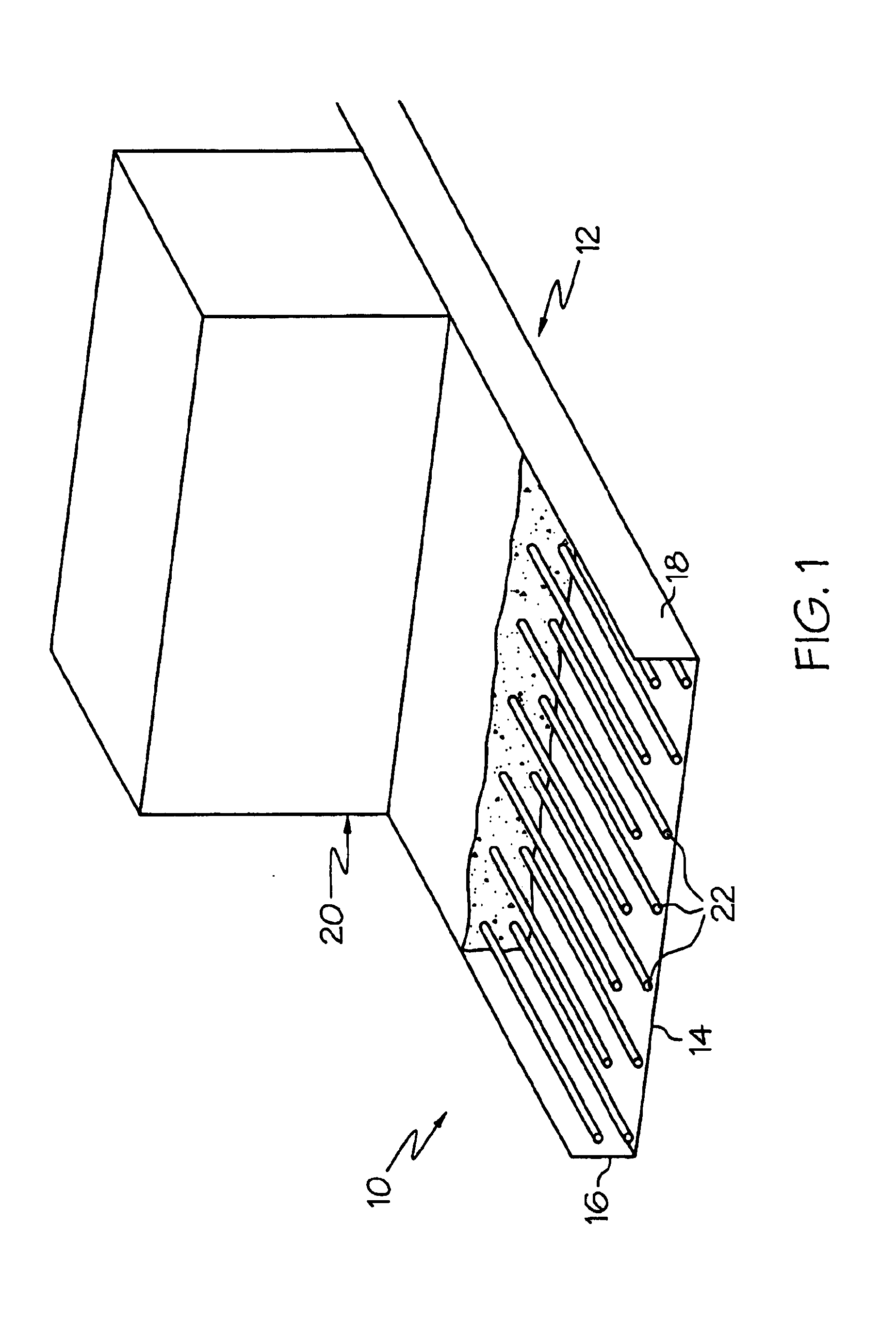
[0025]With reference to the Figures, the inventive concrete slabs, panels or planks of the invention are formed with a standard concrete casting apparatus as shown in U.S. Pat. Nos. 3,217,375; 3,523,343; 4,004,874; 4,289,293 and 4,457,682, the disclosures of which are incorporated herein by reference. Basically, as shown in FIG. 1, such apparatus 10 includes a casting bed 12 that is either stationary or is driven along rails. The casting bed 12 has a bottom pallet 14 and side walls 16, 18. A concrete dispensing hopper 20 is shown in schematic form and can be of any of the current hoppers used to distribute concrete onto a moving bed. Alternatively, the hopper 20 may move relative to a stationary bed. Lower and upper prestressed cables, 22, 23, respectively, are positioned along the length of the bed 12.

[0026]FIG. 2 shows a cross-sectional view of a completed concrete panel 26 of the invention. The panel includes spaced foam billets 30 between each of the prestressed cables 22. When ...


PUM

PropertyMeasurementUnit
Lengthaaaaaaaaaa

Abstract

A method for casting hollow core concrete panels includes the use of raft connectors to hold a plurality of spaced foam billets in place during the manufacture to create panel or plank with spaced foam-filled cores. The panels include billets that form longitudinal voids that allows utilities to be run through the lengths of the concrete panels.

Description

[0001]This application is a continuation-in-part of application Ser. No. 10 / 289,819 filed Nov. 7, 2002.STATEMENT REGARDING FEDERALLY SPONSORED RESEARCH OR DEVELOPMENT[0002]Not Applicable.BACKGROUND OF THE INVENTION[0003]This invention relates to a method for casting hollow core concrete panels in which the hollow cores are made by the use of foam billets held in place during the pours by using a raft connector. Extruders are eliminated via the invention herein. This represents the only hollow core concrete panel which may include cast in openings. This invention is an improvement over U.S. patent application Ser. No. 10 / 289,819 filed Nov. 7, 2002 by the same owner.[0004]Previously, hollow core concrete panels have been formed by many methods, including single and multiple pass casting using moving beds and with stationary beds. The hollow cores are made by using slipform extruders that leave core material in place over which concrete is formed. Once cured, the panels are cut to leng...

Claims


Application Information

Patent Timeline
IPC IPC(8): B28B23/00E04B5/02E04C2/288E04C5/01E04C2/26E04C5/06E04C5/16
CPCB28B23/0025B28B23/0056B28B23/0068E04B5/04E04C2/288E04C2/2885E04C5/0622E04C5/16
Inventor LEJEUNE, MICHAELKUCKHAHN, THOMASHENSLEY, JASONHUNT, BILLYWESEN, RICHARDNOVOTNY, JOSEPHHALL, DONALD
Owner FABCON
Learn More