
Method for controlling a dual clutch transmission

a transmission and clutch technology, applied in mechanical equipment, transportation and packaging, gearing, etc., can solve the problems of affecting the operation of the transmission, and requiring a large amount of physical interaction on the part of the operator, so as to reduce the complexity of the hydraulic system and reduce the number of required components

Active Publication Date: 2005-10-11
BORGWARNER INC
View PDF23 Cites 62 Cited by
  • Summary
  • Abstract
  • Description
  • Claims
  • Application Information

AI Technical Summary

Benefits of technology

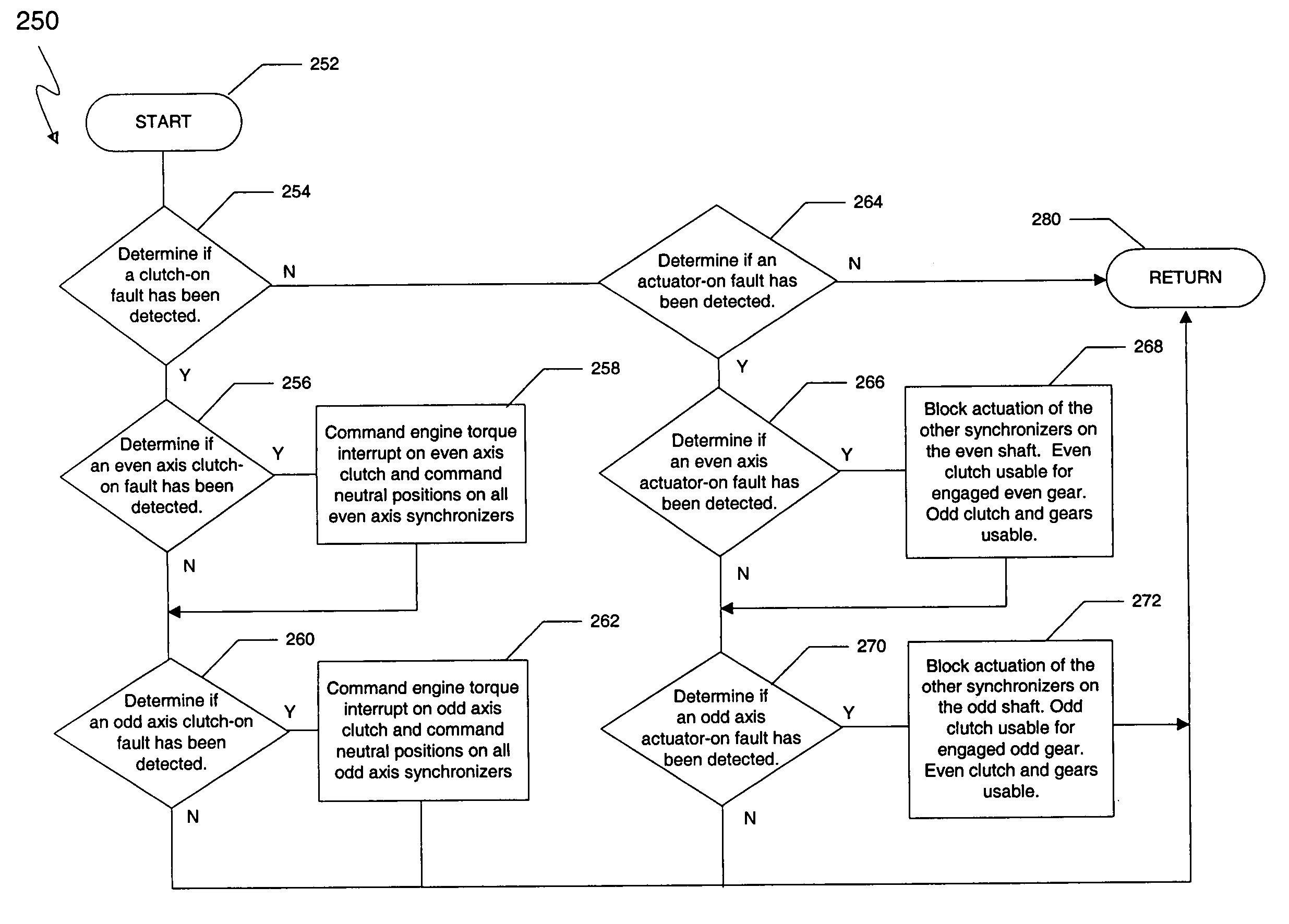
The present invention provides a method for controlling the hydraulic actuation of clutches and synchronizers in a dual clutch transmission in the event of a clutch or synchronizer fault. The method allows for separate handling of clutch and synchronizer actuator faults, avoiding a complete shut down of one of the axis of the transmission in response to an actuator-on fault. The method also simplifies the hydraulic control system and reduces the complexity of the hydraulic system and the number of required components.

Problems solved by technology

One disadvantage of the manual transmission is that there is an interruption in the drive connection during gear shifting.
This results in losses in efficiency.
In addition, there is a great deal of physical interaction required on the part of the operator to shift gears in a vehicle that employs a manual transmission.
Although conventional automatic transmissions avoid an interruption in the drive connection during gear shifting, they suffer from the disadvantage of reduced efficiency because of the need for hydrokinetic devices, such as torque converters, interposed between the output of the engine and the input of the transmission for transferring kinetic energy therebetween.
In addition, automatic transmissions are typically more mechanically complex and therefore more expensive than manual transmissions.
Fluid couplings have inherent slip.
The inherent slip reduces the efficiency of the torque converter.
While torque converters provide a smooth coupling between the engine and the transmission, the slippage of the torque converter results in a parasitic loss, thereby decreasing the efficiency of the entire powertrain.
The power required to drive the pump and pressurize the fluid introduces additional parasitic losses of efficiency in the automatic transmission.
However, even with the inherent improvements of these newer automated transmissions, they still have the disadvantage of a power interruption in the drive connection between the input shaft and the output shaft during sequential gear shifting.
Power interrupted shifting results in a harsh shift feel that is generally considered to be unacceptable when compared to smooth shift feel associated with most conventional automatic transmissions.
While these power-shift dual clutch transmissions overcome several drawbacks associated with conventional transmissions and the newer automated manual transmissions, it has been found that controlling and regulating the automatically actuated dual clutch transmissions is a complicated matter and that the desired vehicle occupant comfort goals have not been achievable in the past.
Conventional control schemes and methods have generally failed to provide this capability.
However, they lack the ability to adapt the operation of the dual clutch transmission in deference to the type of fault that occurs.
However, this is a drastic and unnecessary approach in response to an “actuator-on” fault, especially considering that the great majority of stuck engagement type faults are actuator and synchronizer related rather than clutch related.
Thus, the manner in which conventional dual clutch transmission control methods respond to faults and control the transmission's hydraulic circuit is limited.
Further, current control methods lack the ability to provide for different types of control over the transmission in response to the distinctly different clutch-on fault and actuator-on fault.

Method used


Image

  • Method for controlling a dual clutch transmission
  • Method for controlling a dual clutch transmission
  • Method for controlling a dual clutch transmission

Examples


Embodiment Construction

)

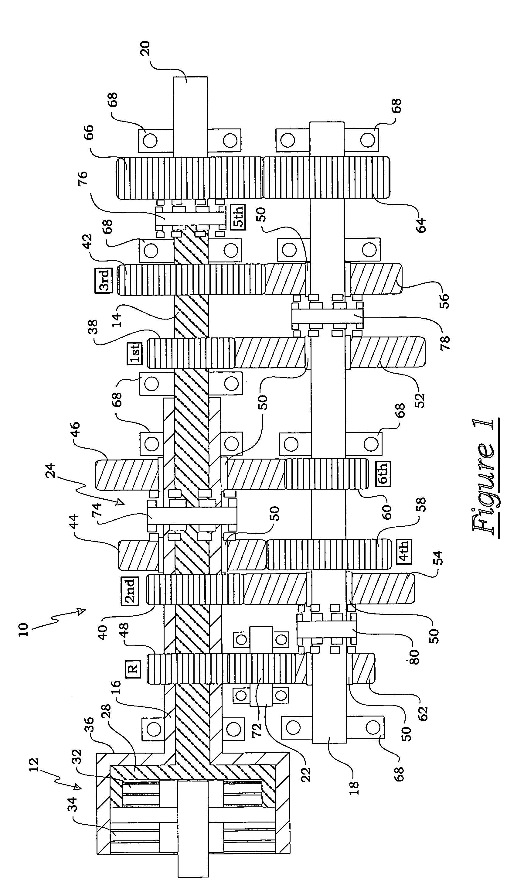
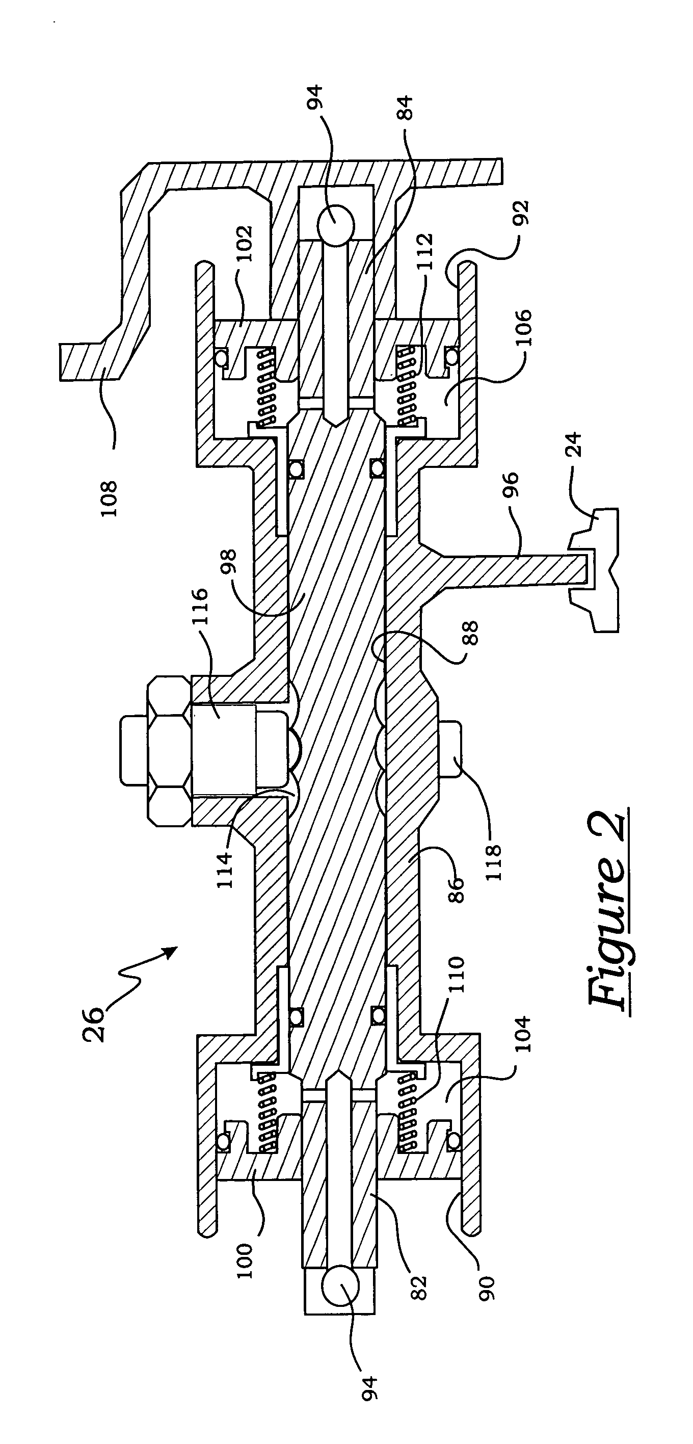
[0023]A representative dual clutch transmission that may be controlled by the present invention is generally indicated at 10 in the schematic illustrated in FIG. 1. Specifically, as shown in FIG. 1, the dual clutch transmission 10 includes a dual, coaxial clutch assembly generally indicated at 12, a first input shaft, generally indicated at 14, a second input shaft, generally indicated at 16, that is coaxial to the first, a counter shaft, generally indicated at 18, an output shaft 20, a reverse counter shaft 22, a plurality of synchronizers, generally indicated at 24, and a plurality of shift actuators generally indicated at 26 (FIG. 2).

[0024]The dual clutch transmission 10 forms a portion of a vehicle powertrain and is responsible for taking a torque input from a prime mover, such as an internal combustion engine, and transmitting the torque through selectable gear ratios to the vehicle drive wheels. The dual clutch transmission 10 operatively routes the applied torque from the en...


PUM


Abstract

A method of controlling the hydraulic actuation of the clutches and the synchronizers in a dual clutch transmission in the event of a clutch or synchronizer fault. The method includes the steps of determining which clutch is faulted when a clutch-on fault is detected, then commanding an interruption of engine torque to the faulted clutch and a neutralization of all synchronizers of the same axis shaft as the faulted clutch. The method further senses if a synchronizer actuator-on fault has occurred, then determines which synchronizer is faulted if an actuator-on fault has is detected. The method steps further include preventing the further actuation of the other synchronizers on the same axis shaft as the faulted actuator.

Description

BACKGROUND OF THE INVENTION[0001]1. Field of the Invention[0002]The present invention relates, generally to the control of a dual clutch transmission and, more specifically, to a method for controlling the hydraulic actuation of the clutches and the synchronizers in a dual clutch transmission in the event of a clutch or synchronizer fault.[0003]2. Description of the Related Art[0004]Generally speaking, land vehicles require a powertrain consisting of three basic components. These components include a power plant (such as an internal combustion engine), a power transmission, and wheels. The power transmission component is typically referred to simply as the “transmission.” Engine torque and speed are converted in the transmission in accordance with the tractive-power demand of the vehicle. Presently, there are two typical transmissions widely available for use in conventional motor vehicles. The first, and oldest type is the manually operated transmission. These transmissions include...

Claims


Application Information

Patent Timeline
Patent Type & Authority Patents(United States)
IPC IPC(8): F16H61/688F16H61/12F16H61/68B60W10/00B60K23/00F16D25/12F16H3/00F16H61/16F16H61/684
CPCF16H61/12F16H61/688F16H3/006F16H2061/1224Y10T477/79F16H2061/1288F16H2061/1276Y10S477/906Y10T477/75F16H2061/128
Inventor KOENIG, MELISSA
Owner BORGWARNER INC
Learn More