
Curve-dependent engine drag-torque control

a curvature-dependent, engine technology, applied in the direction of process and machine control, tractors, instruments, etc., can solve the problems of further reducing cornering stability, affecting the stability of the driving wheel of the vehicle, and the magnitude and duration of the slippage are clearly too great to achieve the necessary cornering stability of the vehicle, so as to increase the slip threshold and reduce the extent of wheel slippage. the effect of a marked reduction

Inactive Publication Date: 2005-10-04
ROBERT BOSCH GMBH
View PDF15 Cites 10 Cited by
  • Summary
  • Abstract
  • Description
  • Claims
  • Application Information

AI Technical Summary

Benefits of technology

The present invention relates to a control system for vehicles that improves stability and reduces slip during driving on low-coefficient-of-friction roadways. The system recognizes when the vehicle is cornering on a road with low friction and adjusts the electronic stability control (ESC) to make it more sensitive than normal driving. This helps to reduce the extent and duration of the wheel slip. The system uses sensors to detect the speed of the non-driven wheels to determine the coefficient of friction of the road. It also calculates an increased augmenting torque to compensate for hard clutch engagement or downshift operations, and a follow-up augmenting torque to prevent the vehicle from going into a slip state. The system sets the slip thresholds for the driven wheels based on the vehicle speed, the coefficient of friction, and the curve radius. Overall, the invention improves the vehicle's ability to safely and efficiently negotiate corners on low-friction roads.

Problems solved by technology

When shifting down or when releasing the accelerator abruptly on a slippery roadway, the driven wheels of a vehicle may slip due to the braking action of the engine.
Especially when cornering on a slippery roadway, this wheel slip results in a further reduction of the cornering stability.
Particularly for vehicles with rear-wheel drive, the lack of cornering stability can lead to critical driving situations such as, for example, the breakaway of the vehicle tail.
However, when cornering on a slippery roadway (low coefficient of friction), the magnitude and duration of the slippage is clearly too great to achieve the necessary cornering stability of the vehicle.
The danger thereby exists that the vehicle will go out of its lane.

Method used


Image

  • Curve-dependent engine drag-torque control
  • Curve-dependent engine drag-torque control
  • Curve-dependent engine drag-torque control

Examples


Embodiment Construction

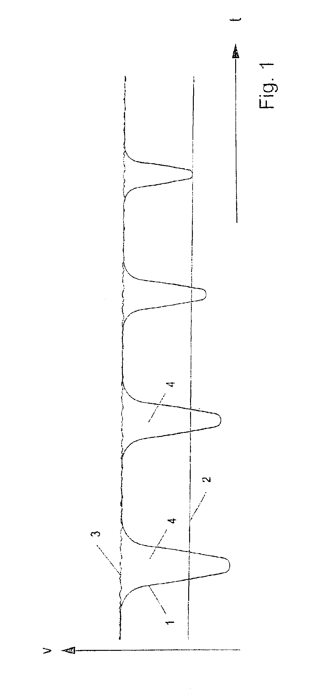
[0030]Reference is made to the introductory part of the specification regarding the clarification of FIG. 1.

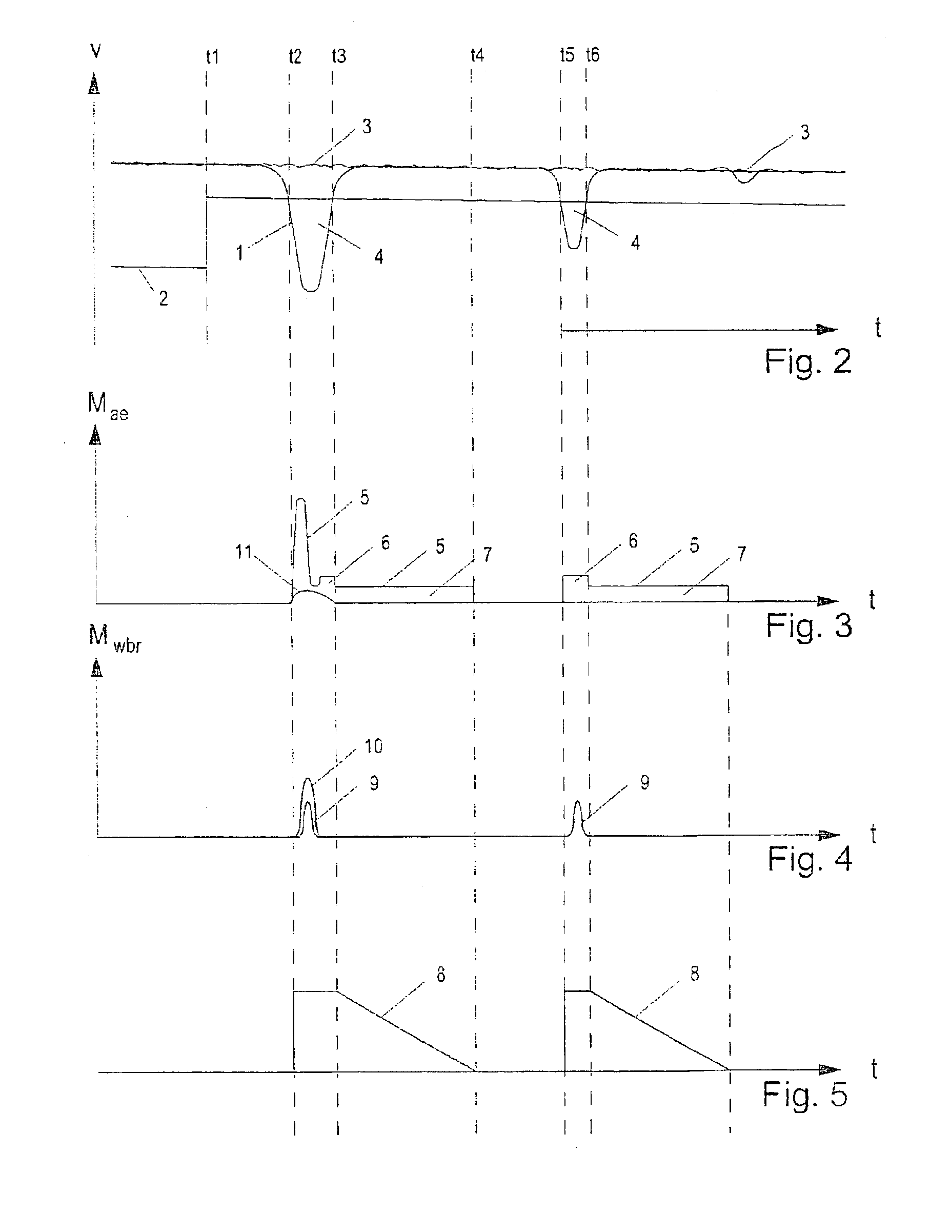
[0031]FIG. 2 shows speed profile 1 of a driven wheel in comparison to vehicle speed 3. At point of time t1, the device for detecting curves and coefficients of friction detects that the vehicle is cornering on a roadway having a low coefficient of friction, whereupon slip threshold 2 is increased abruptly. The EDC control is thus adjusted to be considerably more sensitive.

[0032]Shortly prior to point of time t2, one or both driven wheels go into drag slip. In the following, wheel speed 1 decreases sharply compared to vehicle speed 3.

[0033]At point of time t2, wheel speed 1 drops below increased slip threshold 2, whereby the EDC control commences. The EDC calculates an augmenting torque Mae composed first of all of a slip-proportional component Mlamb (=slip*constant), and secondly, of a component Mwbr corresponding to the drivetrain acceleration. The latter is designated as rot...


PUM


Abstract

An engine drag-torque control, particularly for motor vehicles, in which the engine torque is increased by an EDC augmenting torque when the driven wheels drop below a slip threshold due to the braking action of the engine and exhibit a brake slip which is too high. To improve the vehicle control during cornering on a roadway having a low coefficient of friction, it is provided to increase the slip threshold for the driven wheels to thereby set the drag-torque control to be more sensitive.

Description

FIELD OF THE INVENTION[0001]The present invention relates to an engine drag-torque control (EDC) for motor vehicles, as well as a corresponding method.BACKGROUND INFORMATION[0002]When shifting down or when releasing the accelerator abruptly on a slippery roadway, the driven wheels of a vehicle may slip due to the braking action of the engine. In order to continue to ensure sufficient directional stability of the vehicle, the EDC raises the engine torque by giving gas lightly as soon as one driven wheel has dropped below a predefined slip threshold. The braking of the wheels is thereby reduced to an extent necessary for the directional stability.[0003]Conventional drag-torque controls function reliably when driving on straight roads, but allow too much wheel slip in curves. Especially when cornering on a slippery roadway, this wheel slip results in a further reduction of the cornering stability. Particularly for vehicles with rear-wheel drive, the lack of cornering stability can lead...

Claims


Application Information

Patent Timeline
Patent Type & Authority Patents(United States)
IPC IPC(8): B60K28/16B60T8/175B60T8/1763F02D29/02
CPCB60K28/16B60T2201/09B60W2550/143B60W2550/148F02D2250/26B60W2552/20B60W2552/40B60W2552/30B60W2540/18
Inventor SAUTER, THOMAS
Owner ROBERT BOSCH GMBH
Learn More