
Light beam generation, and focusing and redirecting device

Inactive Publication Date: 2005-10-04
ALTEA THERAPEUTIC CORP +1
View PDF30 Cites 29 Cited by
  • Summary
  • Abstract
  • Description
  • Claims
  • Application Information

AI Technical Summary

Benefits of technology

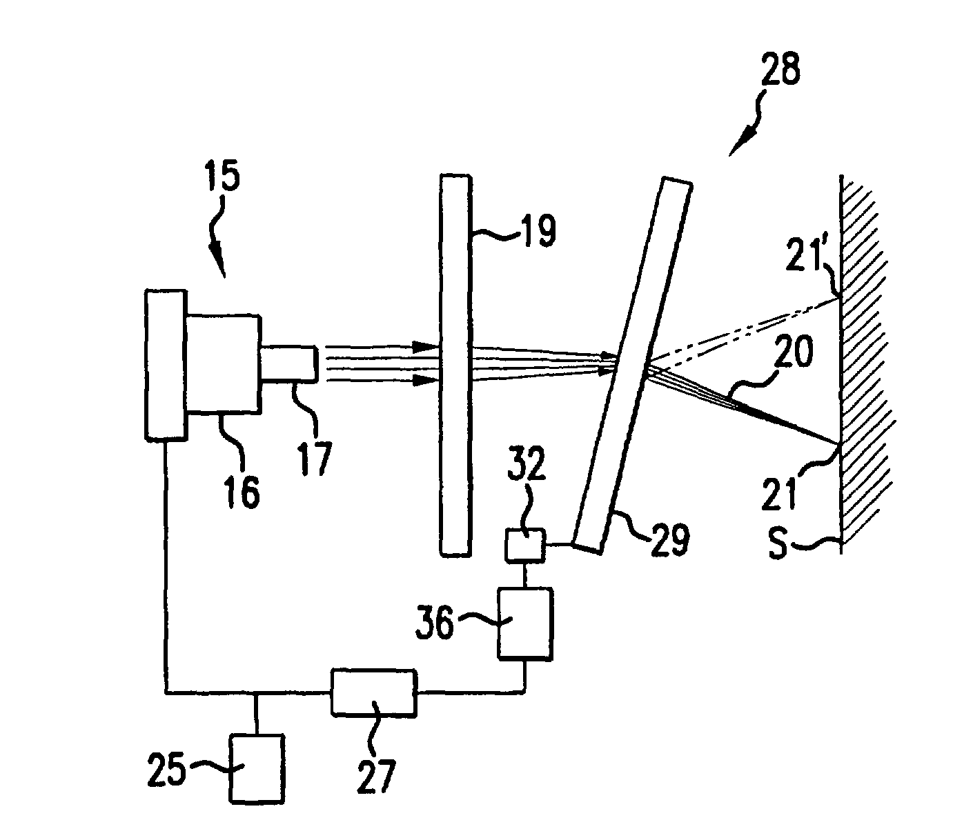
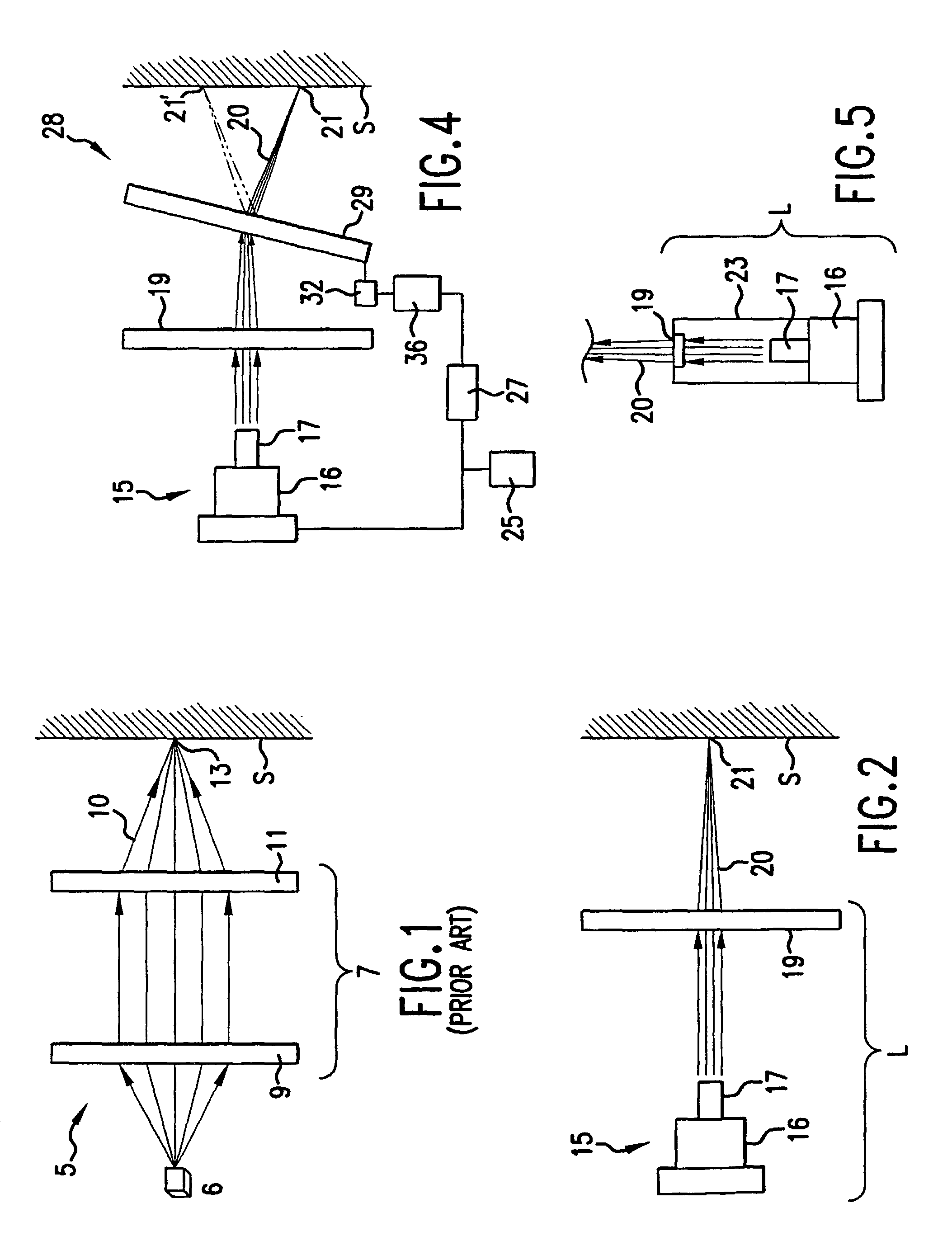
[0010]The present invention provides an improved light beam generation and focusing device adapted for use in emitting and directing at least one focused beam of light to at least two spaced locations on a surface plane, which may include the stratum corneum of a person, and which overcome some of the design deficiencies of the known art. The light beam generation and focusing device of this invention provides a simple and efficient device which allows for a greater degree of flexibility in use when compared to the known types of laser porators. Moreover, the relative simplicity of the device of this invention, when contrasted with the known laser porators, addresses the problems of efficiently and cost effectively focusing at least one beam of light on a surface plane for defining an opening therein, and more preferably for defining an opening in at least two spaced locations therein.
[0011]The invention attains this degree of flexibility, as well as simplicity in design and construction, by providing an improved light beam generation and focusing device having a light source constructed and arranged to emit at least one beam of light, a lens assembly constructed and arranged to focus the at least one beam of light on the surface plane, and which is also constructed and arranged to direct the at least one beam of light to at least two spaced locations on the surface plane.

Problems solved by technology

A problem with the known types of laser ablation / poration devices, however, results from the size of the device necessary to emit and focus a beam of light, and the need or desire to form more than one micropore in the stratum corneum of a person being tested.

Method used


Image

  • Light beam generation, and focusing and redirecting device
  • Light beam generation, and focusing and redirecting device
  • Light beam generation, and focusing and redirecting device

Examples


first embodiment

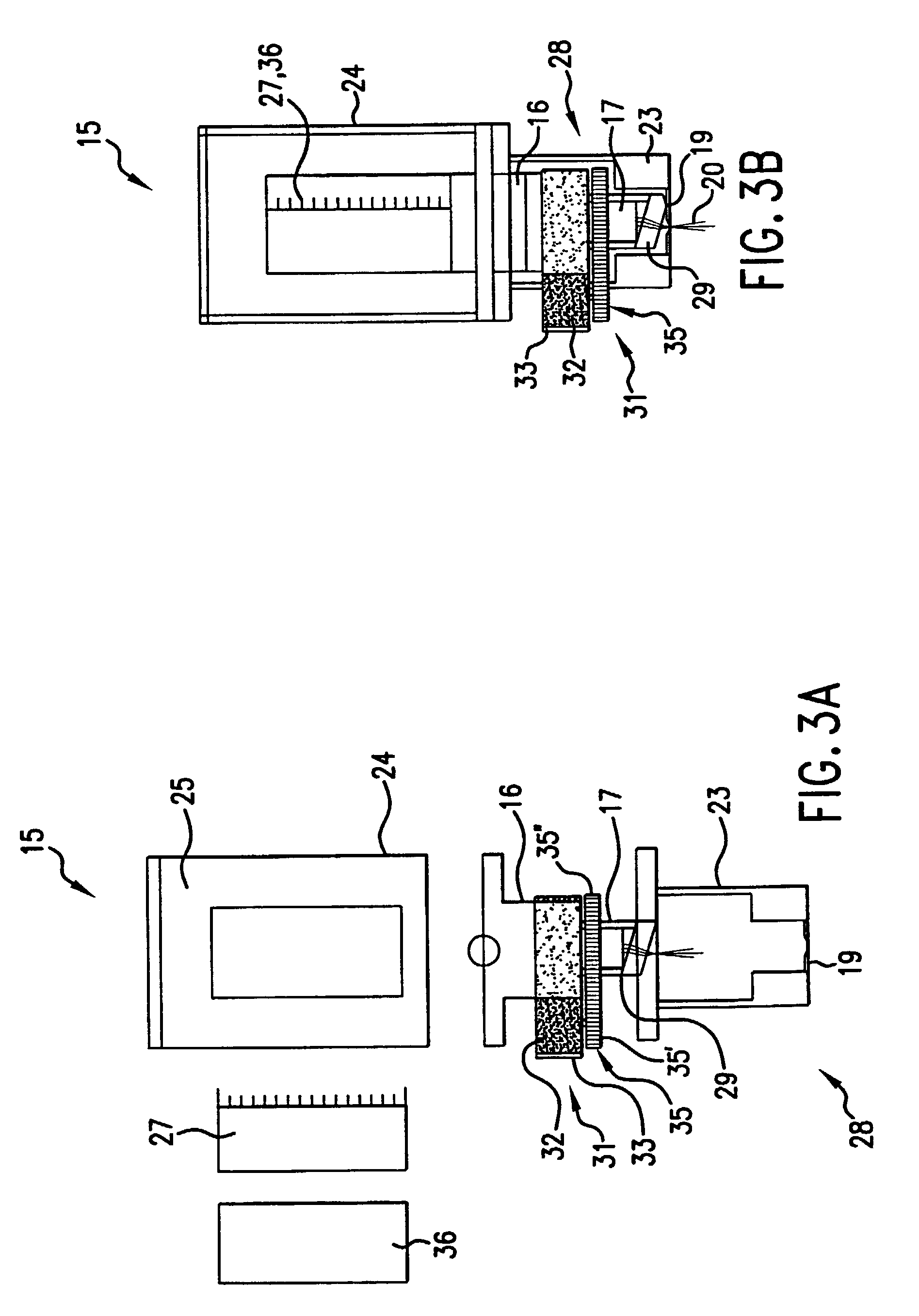
[0034]Referring now in detail to the drawings, in which like reference characters indicate like parts throughout the several views, the light beam generation and focusing device of 15 of this invention is illustrated in FIGS. 2 and 5. The device 15 is provided with a light source 16, here a suitable laser diode, for example those laser diodes manufactured by High Power Devices, or other laser diodes, also referred to as semiconductor diode lasers.

[0035]The light source 16 will preferably be a low-cost solid state laser diode capable of delivering a beam a light having an emission wave length of approximately eight hundred nanometers, or at such other wave lengths and power levels necessary for the intended purposes, which may include, but are not limited to, the forming of a micropore in the stratum corneum of a person's skin. Also, it is anticipated that the laser diode will be sized such that it will be sufficiently small so as to be portable enough to fit within a hand-held housi...

fourth embodiment

[0052]the light beam generation and focusing device 50 is illustrated in FIGS. 7–9. Referring first to FIGS. 7 and 8, in this embodiment of the invention, rather than using a beam steering device 28 as shown in FIGS. 3A–4, a plurality of light sources 51, again laser diodes as described above, are mounted to a common mounting block 52 in the desired geometric pattern to be defined on the surface plane of FIGS. 10–12. Each one of the light sources 51 will be mounted on the mounting block, which also functions as either a ground or an electrode, by an insulated wire bonding pad 54 for forming either the anodic or cathodic lead for the laser diode, respectively, whereas the respective cathodic / anodic leads will be formed through the known wire bonding techniques. The emitting facets of the respective laser diodes will preferably be aligned along the “z” dimensional axis such that when collimated and re-imaged to focus on the surface plane, the focal point of each individual laser diode...


PUM


Abstract

An improved light beam generation and focusing device (15, 50) has a light source (16, 51) constructed and arranged to emit at least one beam of light (20), and a lens assembly (17, 19, 56) constructed and arranged to focus the at least one beam of light on a surface plane. The device is constructed and arranged to sequentially direct the at least one beam of light to at least two spaced locations (21, 21′) on the surface plane. The lens assembly comprises a collimating lens (17), and a spaced focusing lens (19).

Description

CROSS REFERENCE TO RELATED APPLICATIONS[0001]The present application is a 35 U.S.C. § 371 national phase application from, and claims priority to, international application PCT / US00 / 16576, filed Jun. 15, 2000 (published under PCT Article 21(2) in English), which claims priority to U.S. Provisional Application No. 60 / 165,814, filed Nov. 16, 1999 and U.S. Provisional Application No. 60 / 140,003, filed Jun. 18, 1999, which applications are hereby incorporated herein in their entirety.FIELD OF THE INVENTION[0002]The invention relates in general to light beam generation and focusing devices, such as laser porators. More particularly, the invention relates to an improved light beam generation and focusing device adapted to emit at least one focused beam of light directed to at least two spaced locations on a surface plane.BACKGROUND OF THE INVENTION[0003]The use of laser porators for forming micropores in the stratum corneum has proven to be an important advancement in the healthcare field...

Claims


Application Information

Patent Timeline
IPC IPC(8): F21V14/06F21V14/00A61B17/00A61B18/20
CPCA61B18/20A61B2017/00765A61B2018/2085A61B2018/20351A61B2018/20355A61B2018/2025
Inventor KUMAR, KRISHNA S.LINCOLN, DANNY F.EPPSTEIN, JONATHAN A.HATCH, MICHAEL R.
Owner ALTEA THERAPEUTIC CORP
Learn More