
Contact magnetic printing of magnetic media using actuated magnet poles and stampers

a technology of magnetic media and stampers, applied in the field of disc drive storage, can solve the problems of low frequency errors being laid down in the servo pattern, requiring significant amount of correction, and limiting the overall track density,

Inactive Publication Date: 2005-09-27
SEAGATE TECH LLC
View PDF3 Cites 7 Cited by
  • Summary
  • Abstract
  • Description
  • Claims
  • Application Information

AI Technical Summary

Benefits of technology

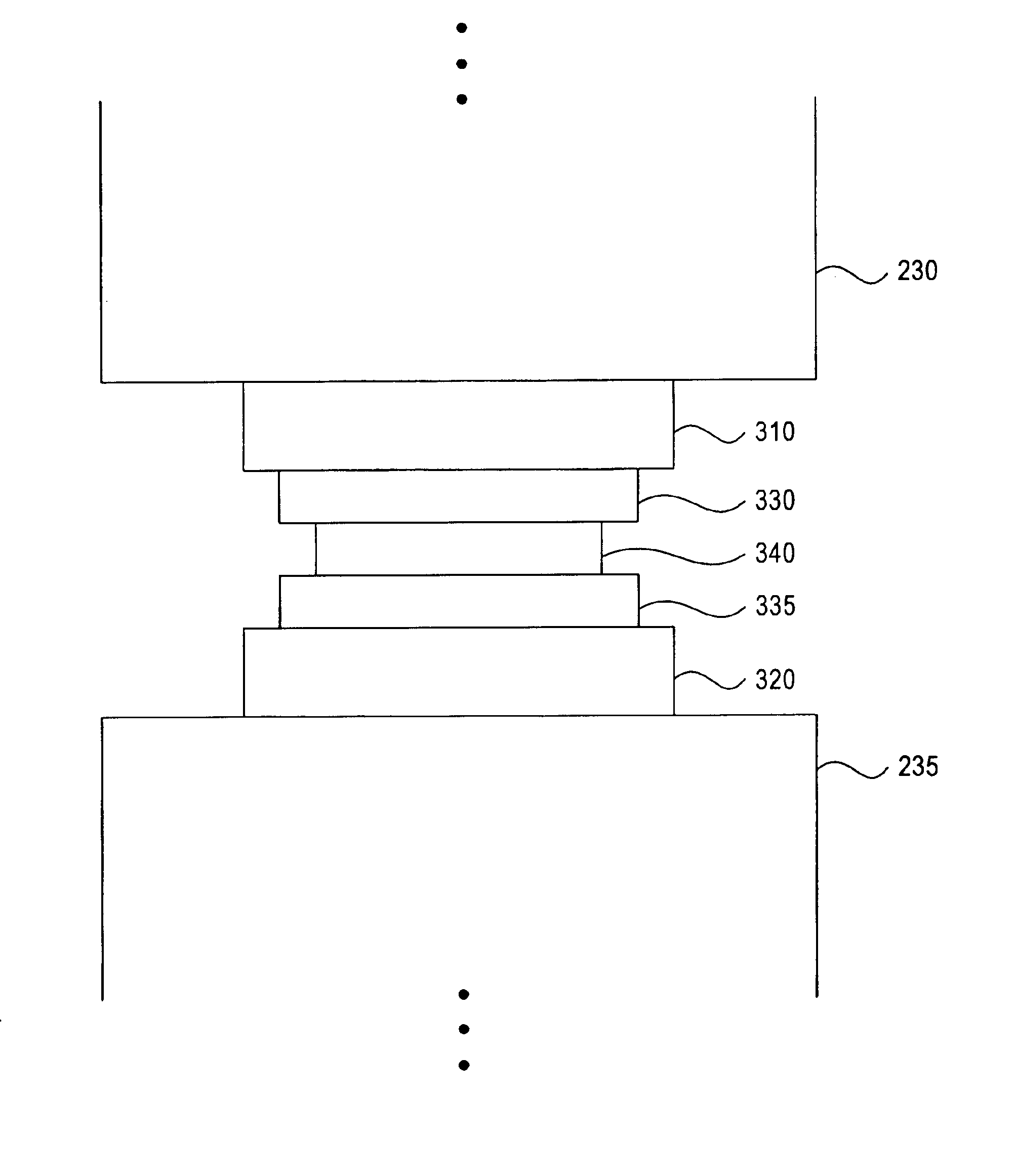
[0012]A system for contact magnetic printing servo patterns onto a magnetic media that does not involve the use of conventional servo writers is disclosed. The apparatus includes a dipole magnet that supplies a magnetic field to a magnetic media, a holder for holding the magnetic media, two stampers with servo patterns and a press for pressing the stampers firmly against the magnetic media while the magnetic media and stampers are exposed to a magnetic field. An elastomer pad is also used to deliver and spread evenly the force of the press on the magnetic media / stamper stack. In the case of single sided printing one stamper can be used instead of two.
[0013]Additionally, a method for contact magnetic printing servo patterns onto a magnetic media that does not involve the use of conventional servo writers is disclosed. The magnetic media to be servo patterned is first positioned against two stampers so that each stamper is abutted against opposite sides of the magnetic media. In the case of single sided printing only one stamper is used and that stamper is abutted against the one side of the magnetic media that is to be servo written. The magnetic media / stampers stack is then loaded and aligned in a system for contact magnetic printing, applying a force on the magnetic media / stampers stack so that they are in firm contact with each other at the interface. A sequence of magnetic fields, of sufficient strength, is then applied for a set time to the magnetic media / stampers stack while it is subjected to the force. An example of a typical sequence of magnetic fields includes applying a first magnetic field of approximately 15 KOe in one direction for a few milliseconds and then applying a second field of approximately 3 KOe is the opposite direction for a few milliseconds. Finally, the magnetic field is removed, the magnetic media / stampers stack is unloaded from the contact magnetic printing apparatus and the stampers and magnetic media are separated.
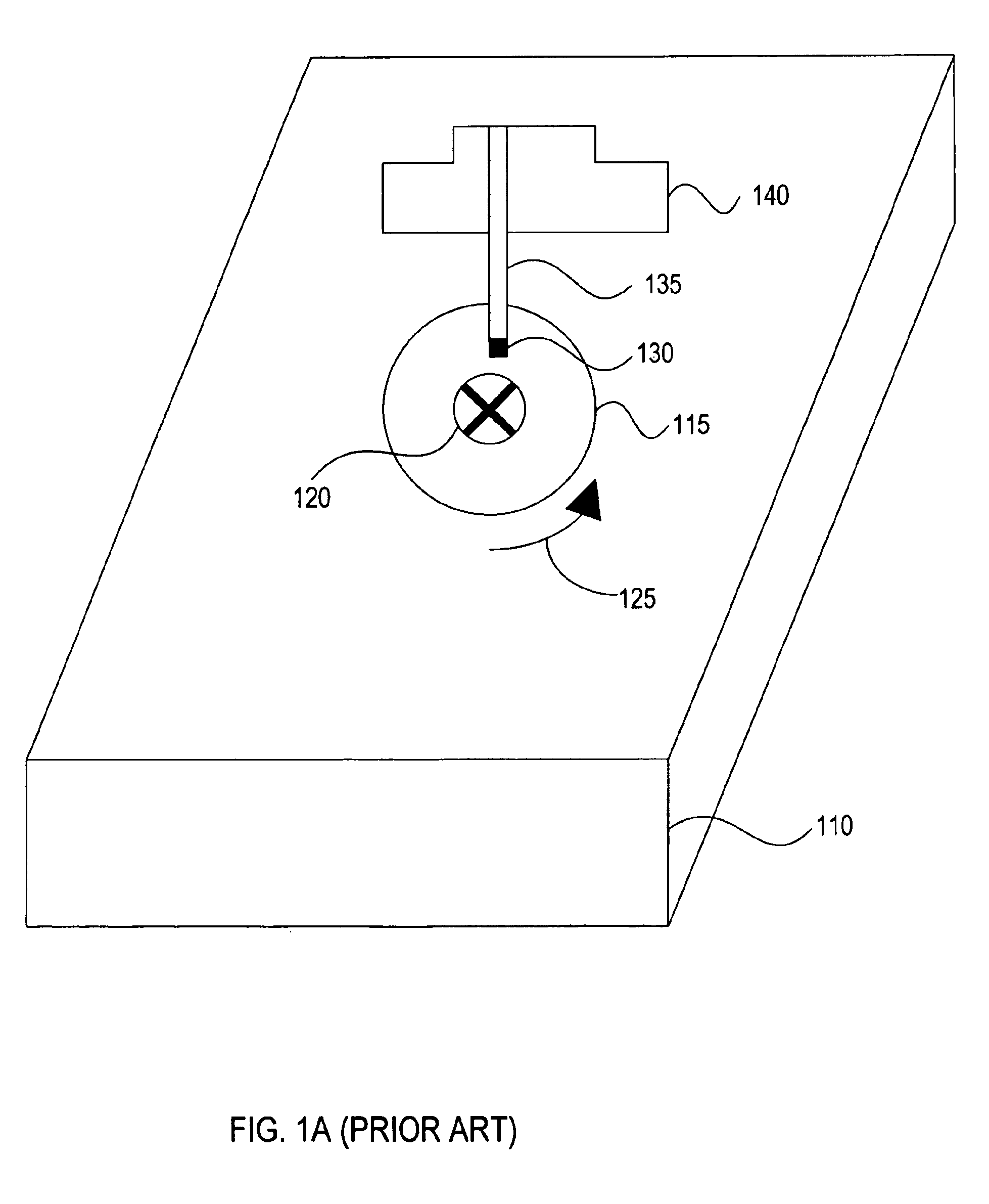
[0014]FIG. 1A is a block diagram showing the writing of servo patterns using conventional servo writers.

Problems solved by technology

When such frequencies are sufficiently severe, the correction required to account for these frequencies can require a significant amount of correction limiting the overall track density that can be achieved in a disc drive design.
One source of error that occurs during the servo writer process is the spindle motor, which includes bearing assemblies with characteristic frequencies that are generated from the rotation of the balls and ball cages within the inner and outer bearing raceways.
These bearing frequencies can result in low frequency errors being laid down in the servo pattern.

Method used


Image

  • Contact magnetic printing of magnetic media using actuated magnet poles and stampers
  • Contact magnetic printing of magnetic media using actuated magnet poles and stampers
  • Contact magnetic printing of magnetic media using actuated magnet poles and stampers

Examples


Embodiment Construction

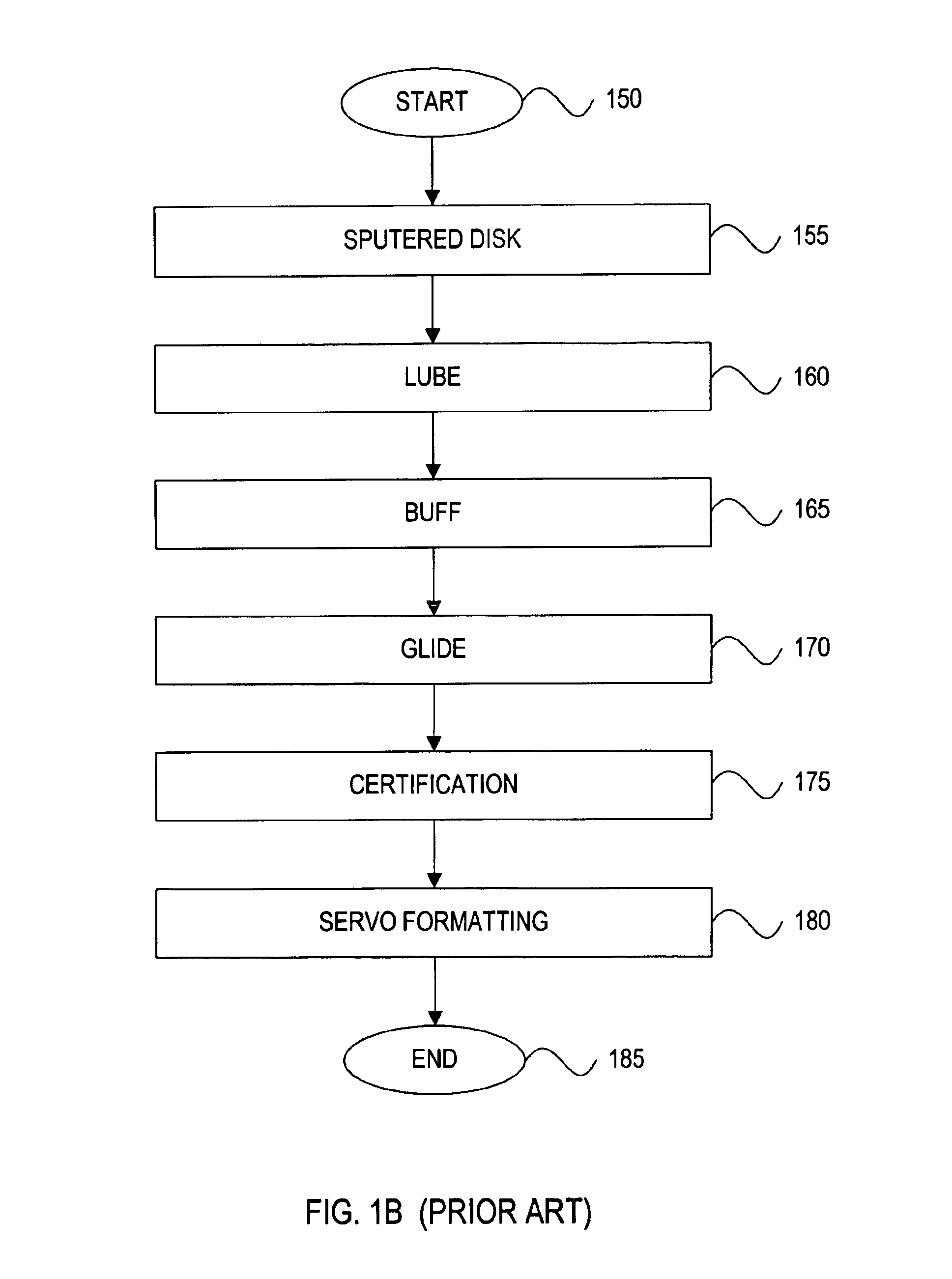
[0024]The invention provides a system and method for creating magnetic patterns on magnetic recording media. In particular, the invention provides a system and method for servo formatting magnetic media using contact magnetic printing.

[0025]FIG. 2 represents a contact magnetic printer, in accordance with one embodiment of the invention, including a frame 210, a press 215, a driving rod 220, a stage 225, a first magnetic pole 230, a second magnetic pole 235, a yoke 240 and a sample holder 245.

[0026]Frame 210 is a support structure typically made of sturdy materials such as iron, aluminum or stainless steel. The main function of frame 210 is to hold up the contact magnetic printer and its components. Additionally, frame 210 can include an antivibration mechanism, such as an air bearing surface, for decoupling the contact magnetic printer from the floor.

[0027]Press 215 is a hydraulic press used to apply force to the sample in a uniaxial direction. Press 215 typically consists of a hydr...


PUM

PropertyMeasurementUnit
diameteraaaaaaaaaa
diameteraaaaaaaaaa
thicknessaaaaaaaaaa

Abstract

A magnetic printing apparatus includes a dipole magnet that supplies a magnetic field to a magnetic media, a holder for holding the magnetic media, a set of stampers with servo patterns and a press for pressing the magnetic media firmly against the stampers while the magnetic media and stampers are being exposed to a magnetic field and a set of elastomer pads to distribute and equalize the force of the press on the magnetic media. Servo formatting, using the contact magnetic printing apparatus, is done by positioning the magnetic media against the stampers. A force is then applied to the magnetic media and stamper so that the two are in firm contact with each other. A sequence of magnetic fields is then applied to the stampers and magnetic media which duplicates the servo patterns of the stamper onto the magnetic media.

Description

[0001]This application claims priority from U.S. provisional application ser. No. 60 / 350,181, filed on Jan. 15, 2002.BACKGROUND OF THE INVENTION[0002]1. Field of the Invention[0003]The present invention relates generally to the field of disc drive storage, and more particularly to contact magnetic printing used to create magnetic patterns on magnetic recording media.[0004]2. Description of the Related Art[0005]Conventional disc drives use magnetic properties of materials to store and retrieve data. Typically, disc drives are incorporated into electronic equipment, such as computer systems and home entertainment equipment, to store large amounts of data in a form that can be quickly and reliably retrieved. The major components of a disc drive include magnetic media in the form of a disk, read-write heads, a motor and software. The magnetic media is rotated by a motor at a constant high speed while the read-write head, which rests on a head gimble assembly, glides over the magnetic me...

Claims


Application Information

Patent Timeline
Patent Type & Authority Patents(United States)
IPC IPC(8): G11B5/00G11B5/86
CPCG11B5/00G11B5/865
Inventor WANG, LI-PINGPRAX, ANDREW GEORGEKUO, DAVID SHAIO-MIN
Owner SEAGATE TECH LLC
Learn More