Method of implementing the kerr effect in an integrated ring resonator (the kerr integrated optical ring filter) to achieve all-optical wavelength switching, as well as all-optical tunable filtering, add-and -drop multiplexing, space switching and optical intensity modulation

Inactive Publication Date: 2005-09-20
FISCHER SYLVAIN G
View PDF2 Cites 59 Cited by
  • Summary
  • Abstract
  • Description
  • Claims
  • Application Information

AI Technical Summary

Benefits of technology

[0010]The present invention relates to an integrated optical ring filter, which consists of an integrated optical circuit containing a ring resonator waveguide surrounded by an upper bus waveguide and a lower bus waveguide. An optical wave, the wavelength of which meets the resonance conditions defined by the core refractive index and the length of the resonator, propagates through the resonator. This optical wave has a high intensity, therefore, it is able to modulate the core refractive index of the resonator through the Kerr effect. This refractive index change shifts the resonant conditions of the resonator. The optical wave achieves thereby the shifting of the resonance curves of the optical ring filter.
[0011]A second optical wave, the wavelength of which meets the resonance conditions of the ring resonator, propagates through the resonator in the counter-direction with respect to the first optical wave. The shifting of the resonance curves achieved by the first optical wave results in a modulation of the intensity of the second optical wave at its non-resonant port. Through this process, the optical amplitude modulation pattern of the first optical wave can be transferred to the second optical wave. When the optical waves have different resonant wavelengths, the achieved effect is optical wavelength conversion, also referred to as optical wavelength switching.
[0012]Whereas prior arts either cumulate the small phase shift induced by the Kerr effect along a large optical path or make use of the carrier density modulation in a semiconductor waveguide, the present invention stores and cumulates the energy of the incoming optical carrier along a very short path to achieve the required phase shift through the Kerr effect without making use of electrical carrier generation which is a slower process than all-optical nonlinear processes like the Kerr effect. Furthermore, the present invention implements the Kerr effect in an integrated optical ring resonator instead of a non-integrated optical fiber Sagnac interferometer. This Kerr integrated optical ring filter (“K-IORF”) is, therefore, able to trigger a nonlinear effect achieving fast all-optical wavelength switching in a micro and integrated form suitable for use in the telecom industry. In addition, in alternative embodiments and methods of driving the K-IORF, the K-IORF can achieve filtered wavelength tuning, add-and-drop multiplexing, space switching and intensity modulation depending on the way it is actually driven. These features are relevant to the optical telecom industry and to other industries that make use of optical sensing, including civil engineering (monitoring), ship and aircraft industries (structural health monitoring) and automotive industry (cars, turbines).

Problems solved by technology

A primary technological barrier to fully functional Optical Networks is the need for all-optical switches.
As a result, the first optical wave can induce destructive or constructive interference of the second optical wave at the output of the interferometer.
However, as the strength of the Kerr effect is quite weak in a glass optical fiber (˜3·10−20 m2 / W, Govind P. Agrawal, Fibre-Optic Communication Systems, p.
62, second edition, Wiley-Interscience, 1997), the length of the optical loop must be very long (more than 10 km), rendering the technology of this prior art far too cumbersome for implementation in telecom or other industries requiring the use of micro-devices.
Although wavelength conversion is achieved, this technique suffers from sensitivity to light polarization and wavelength chirping in the amplifying medium and, therefore, limits conversion efficiency and bandwidth.

Method used


Image

  • Method of implementing the kerr effect in an integrated ring resonator (the kerr integrated optical ring filter) to achieve all-optical wavelength switching, as well as all-optical tunable filtering, add-and -drop multiplexing, space switching and optical intensity modulation
  • Method of implementing the kerr effect in an integrated ring resonator (the kerr integrated optical ring filter) to achieve all-optical wavelength switching, as well as all-optical tunable filtering, add-and -drop multiplexing, space switching and optical intensity modulation
  • Method of implementing the kerr effect in an integrated ring resonator (the kerr integrated optical ring filter) to achieve all-optical wavelength switching, as well as all-optical tunable filtering, add-and -drop multiplexing, space switching and optical intensity modulation

Examples


Embodiment Construction

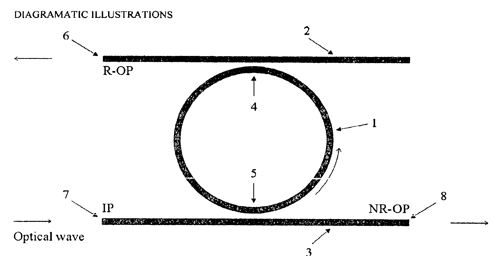
[0013]FIG. 1K-IORF top view.

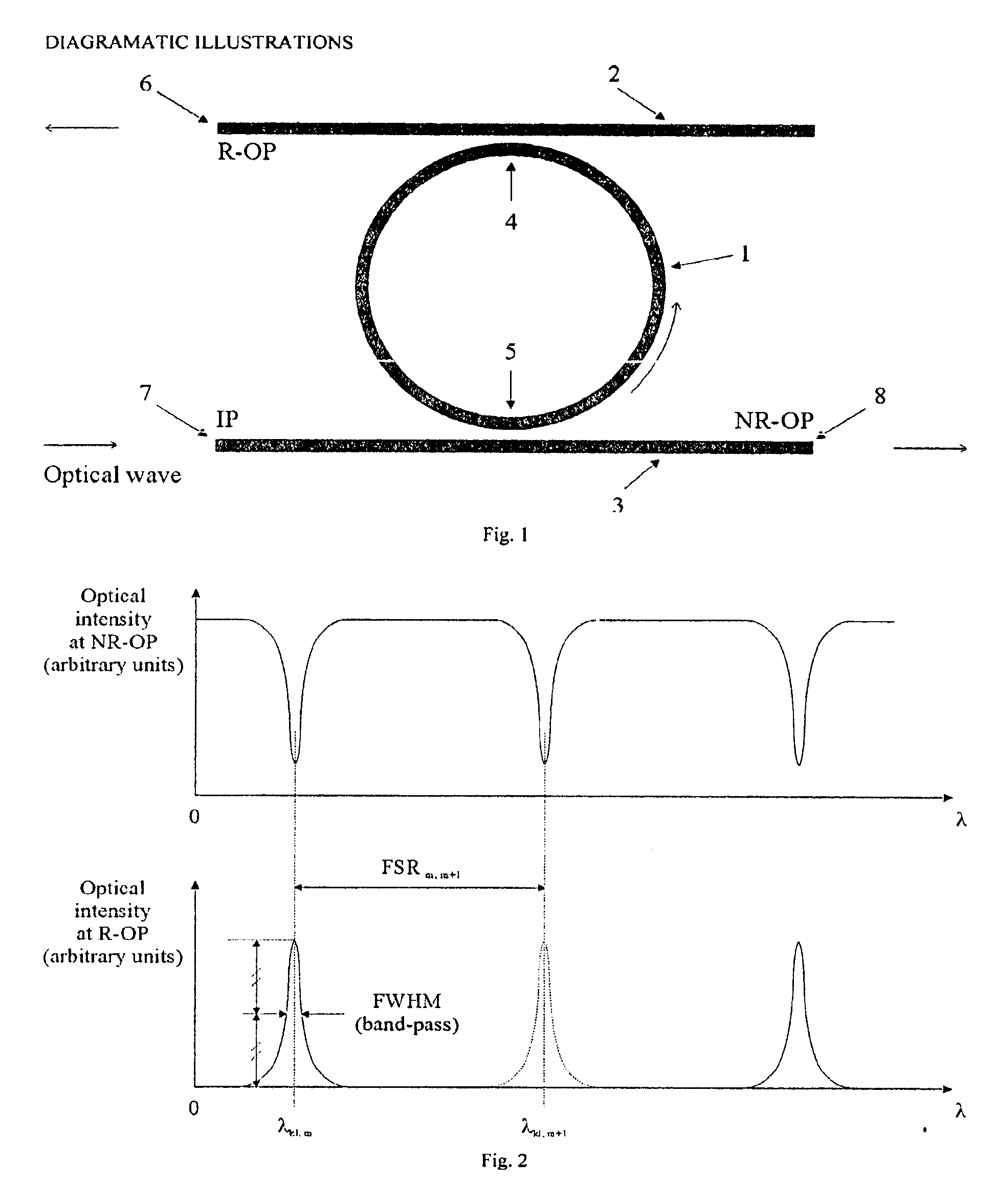
[0014]FIG. 2 Resonant curves of the ring resonator.

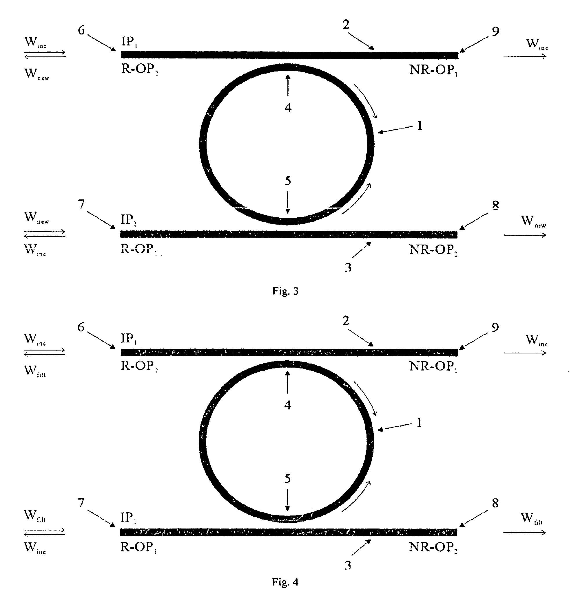
[0015]FIG. 3K-IORF, resonance shifting and wavelength switching.

[0016]FIG. 4K-IORF as an all-optical tunable filter.

[0017]FIG. 5 Tuning of the resonance curves of the K-IORF as an all-optical tunable filter.

[0018]FIG. 6K-IORF as an all-optical add-and-drop multiplexer.

[0019]FIG. 7K-IORF as an all-optical optical modulator.

[0020]FIG. 8 Tuning of the resonance curves of the K-IORF as an all-optical optical modulator.

[0021]FIG. 9K-IORF with arc-buses.

[0022]FIG. 10 Race-track K-IORF top view.

[0023]FIG. 11 Vertical coupler K-IORF.

DETAILED DESCRIPTION OF THE INVENTION

[0024]The Kerr Integrated Optical Ring Filter (K-IORF) sketched in FIG. 1 consists of:[0025]an optical ring resonator (the “ring”) (FIG. 1, 1);[0026]an upper waveguide or upper bus waveguide (the “upper bus”) (FIG. 1, 2); and[0027]a lower waveguide or lower bus waveguide (the “lower bus”) (FIG. 1, 3).

1. Manufacturing of the K-IORF.

[0028]The K-IORF ...


PUM


Abstract

The present invention relates to an integrated optical ring resonator waveguide surrounded by an upper bus and a lower bus waveguide. A first resonant and intense optical wave is coupled into the upper bus whereas a second resonant optical wave is coupled into the lower bus. These resonant waves propagate from one bus to the other through the resonator in opposite directions. The first wave modulates the core refractive index of the resonator (Kerr effect) and thereby shifts the resonant conditions of the resonator. This results in the amplitude modulation of the second wave at its non-resonant port. Through this process, the optical amplitude modulation pattern of the first wave is transferred to the second wave. Optical wavelength switching is achieved when the waves have different wavelengths. In alternative embodiments and methods of driving the resonator, the resonator can achieve filtered wavelength tuning, add-and-drop multiplexing, space switching and intensity modulation.

Description

[0001]Method of implementing the Kerr effect in an integrated ring resonator (the Kerr Integrated Optical Ring Filter) to achieve all-optical wavelength switching, as well as all-optical tunable filtering, add-and-drop multiplexing, space switching and optical intensity modulation.CROSS-REFERENCE TO RELATED APPLICATIONS[0002]Not ApplicableSTATEMENT REGARDING FEDERALLY SPONSORED RESEARCH AND DEVELOPMENT[0003]Not Applicable.REFERENCE TO A MICROFICHE APPENDIX[0004]Not Applicable.BACKGROUND OF THE INVENTION[0005]Optical waveguides are capable of being integrated on different kinds of substrates (e.g. glass, Gas, InP, Si) for the purpose of developing Optical Integrated Circuits (OICs). The optical waveguides can then be used to build integrated micro-devices such as attenuators, filters and multiplexers and to interconnect these devices on the same substrate. The multi-functionality achieved by the different devices in the optical chip allows for the development of advanced optical syst...

Claims


Application Information

Patent Timeline
IPC IPC(8): G02B6/12G02B6/34
CPCG02B6/12007G02F1/035G02B6/29338G02F1/293G02F2203/15
Inventor FISCHER, SYLVAIN G.
Owner FISCHER SYLVAIN G
Why Eureka
Try Eureka