
Rake receiver for a CDMA system, in particular incorporated in a cellular mobile phone

Active Publication Date: 2005-09-20
STMICROELECTRONICS SRL
View PDF8 Cites 41 Cited by
  • Summary
  • Abstract
  • Description
  • Claims
  • Application Information

AI Technical Summary

Benefits of technology

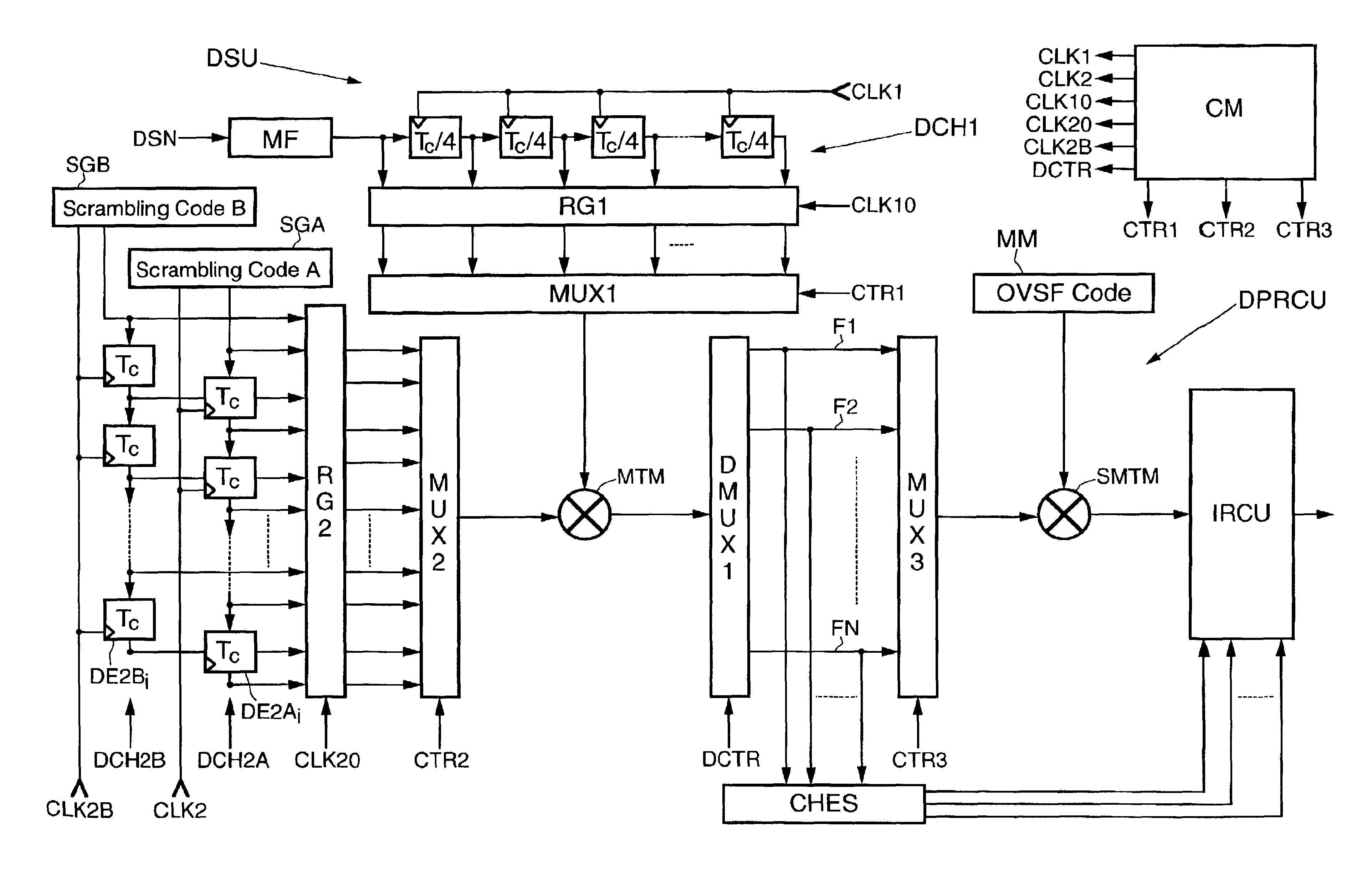
[0013]Another object of the present invention is to provide a rake receiver with a time aligning and descrambling unit having a rather straightforward and flexible hardware structure.
[0018]With such an implementation according to the present invention, the stored samples of the received signal, which are stored in the first delay chain, are used for the fine timing adjustment of the descrambling unit. Since the minimum number of first outputs is equal to Ns+1, the memory size of the delay chain can be considerably reduced.

Problems solved by technology

However, such an approach is hardware consuming since one multiplier is implemented for each path.
Further, a large amount of input memory is needed since it is necessary to take into account the maximum delay spread in the worst case together with the resolution of the analog-to-digital converters.
However, it is difficult to implement independent scrambling code generators for each of the fingers.
If a memory is used for storing all the delayed scrambling codes for all the paths, the addressing scheme of this memory is rather complicated and furthermore, must be modified, if during the transmission, one delay value of one path changes.
The implementation of this approach is even more complicated when several scrambling codes associated with several base stations must be taken into account in the rake receiver.

Method used


Image

  • Rake receiver for a CDMA system, in particular incorporated in a cellular mobile phone
  • Rake receiver for a CDMA system, in particular incorporated in a cellular mobile phone
  • Rake receiver for a CDMA system, in particular incorporated in a cellular mobile phone

Examples


Embodiment Construction

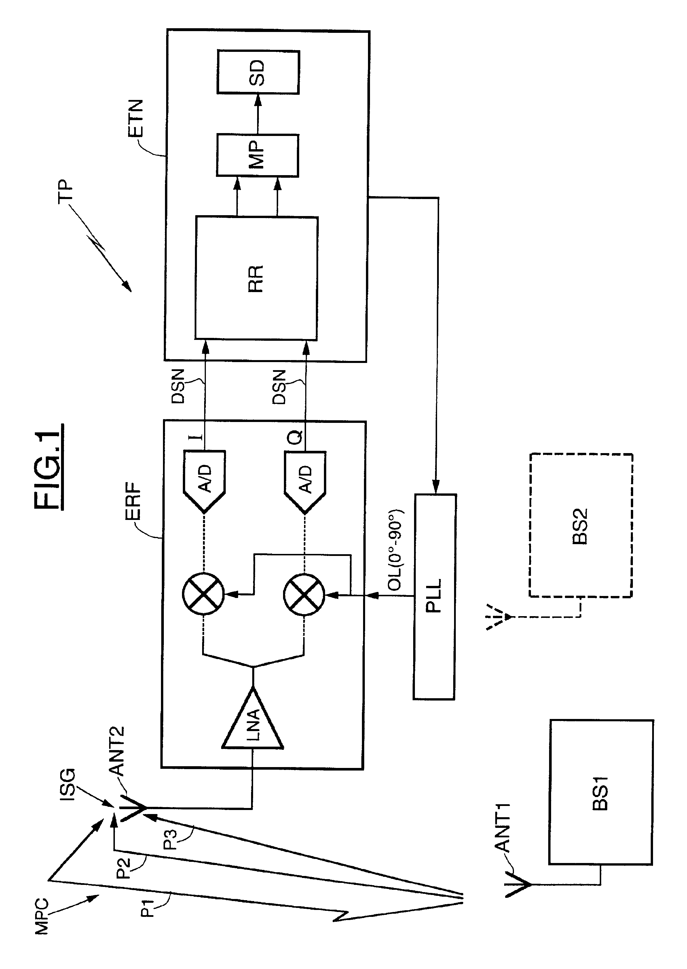
[0043]In FIG. 1, the reference TP denotes a remote terminal such as a cellular mobile phone communicating with a base station BS1. The mobile phone TP comprises, conventionally, an analog radio frequency front end stage ERF connected to an antenna ANT2 for receiving an input signal ISG.

[0044]Conventionally, the stage ERF comprises a low noise amplifier LNA and two processing channels including mixers and conventional filters and amplifiers (not shown). The two mixers receive respectively from a phase locked loop PLL two signals, having mutually a phase difference of 90°. After frequency transposition in the mixers, the two processing channels define respectively two streams I and Q as readily understood by one skilled in the art. After digital conversion by analog-to-digital converters A / D, the two digital streams I and Q are delivered to a digital processing stage ETN.

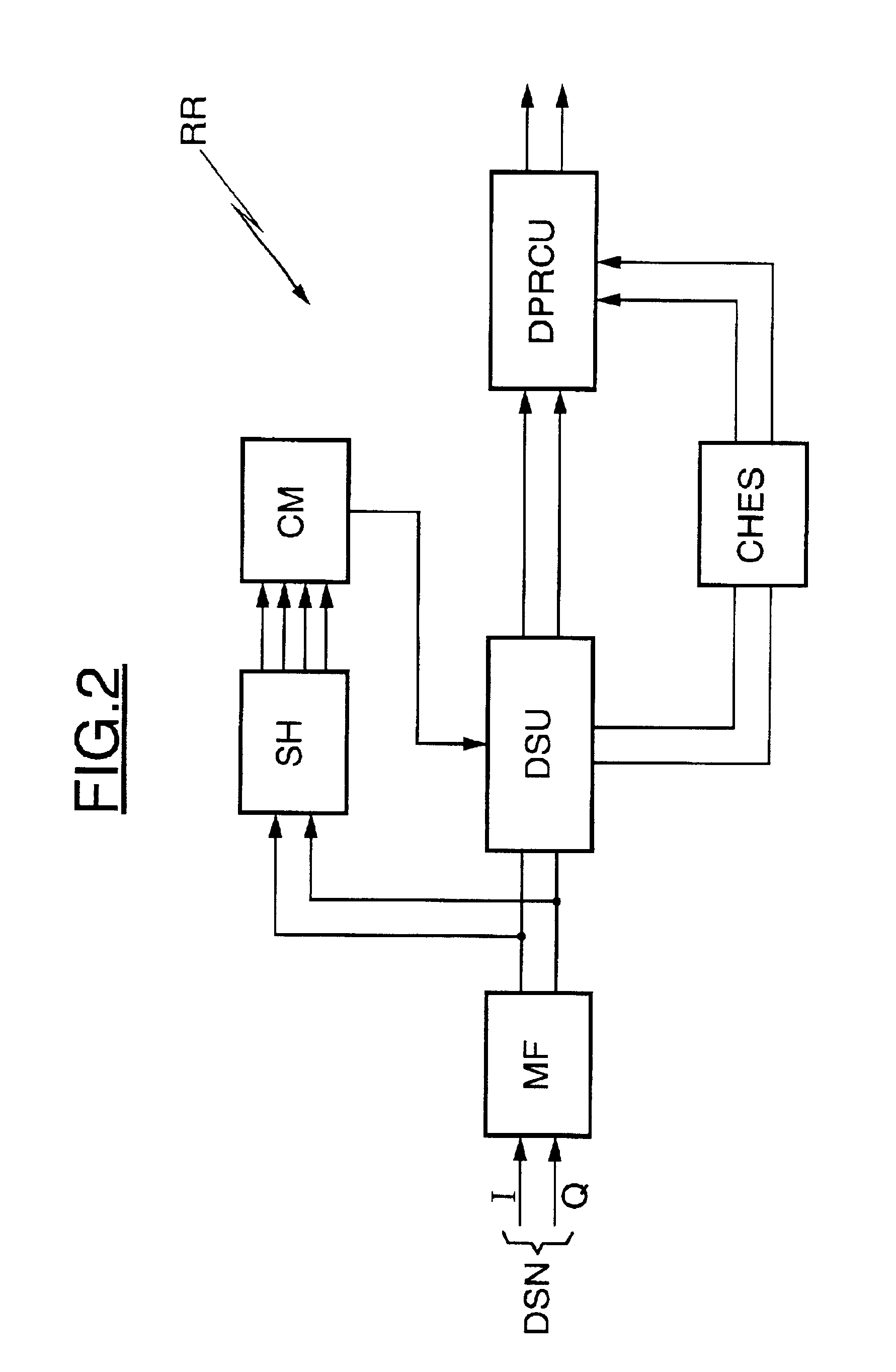
[0045]The digital processing stage ETN comprises a rake receiver RR followed by conventional demapping means MP (de...


PUM


Abstract

A rake receiver uses a delayed version of the received sequence and a delayed version of a scrambling code. The flexible hardware structure of the time-aligning and descrambling unit includes at least two delay chains and one multiplier. By controlling two multiplexers, the delayed versions of the received sequence can be multiplied with an arbitrary scrambling code having an arbitrary phase. During one chip period, one multiplication is performed for each path to be processed.

Description

FIELD OF THE INVENTION[0001]The present invention relates to the field of wireless communication systems, and more particularly, to CDMA systems such as the different CDMA based mobile radio systems including CDMA 2000, Wide Band CDMA, and the IS-95 standard.BACKGROUND OF THE INVENTION[0002]In a wireless communication system, a central base station communicates with a plurality of remote terminals, such as cellular mobile phones. Frequency-Division Multiple Access (FDMA) and Time-Division Multiple Access (TDMA) are the traditional multiple access schemes to provide simultaneous services to a number of terminals. The basic idea behind FDMA and TDMA technics is to slice the available resource into multiple frequency or time slots, respectively, so that multiple terminals can be accommodated without causing interference.[0003]Contrasting these schemes with separate signals in frequency or time domains, Code-Division Multiple Access (CDMA) allows multiple users to share a common frequen...

Claims


Application Information

Patent Timeline
IPC IPC(8): H04B1/707
CPCH04B1/7115H04B1/7117
Inventor BERENS, FRIEDBERT
Owner STMICROELECTRONICS SRL
Learn More