
Thin-walled rubber hose and method of producing the same

a thin-walled rubber and hose technology, applied in the direction of pipes, mechanical equipment, coatings, etc., can solve the problems of difficult molding, difficult process for coating a subsequent outer layer of rubber according to a hose production method of conventional specifications, and collapse of the inner layer, so as to improve permeability resistance, improve elasticity, and improve the effect of productivity

Inactive Publication Date: 2005-09-20
YAMASHITA RUBBER CO LTD
View PDF12 Cites 37 Cited by
  • Summary
  • Abstract
  • Description
  • Claims
  • Application Information

AI Technical Summary

Benefits of technology

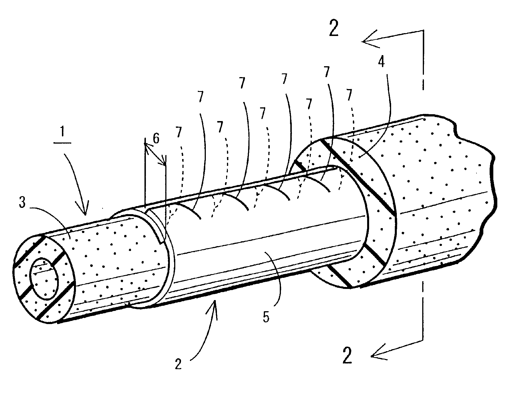
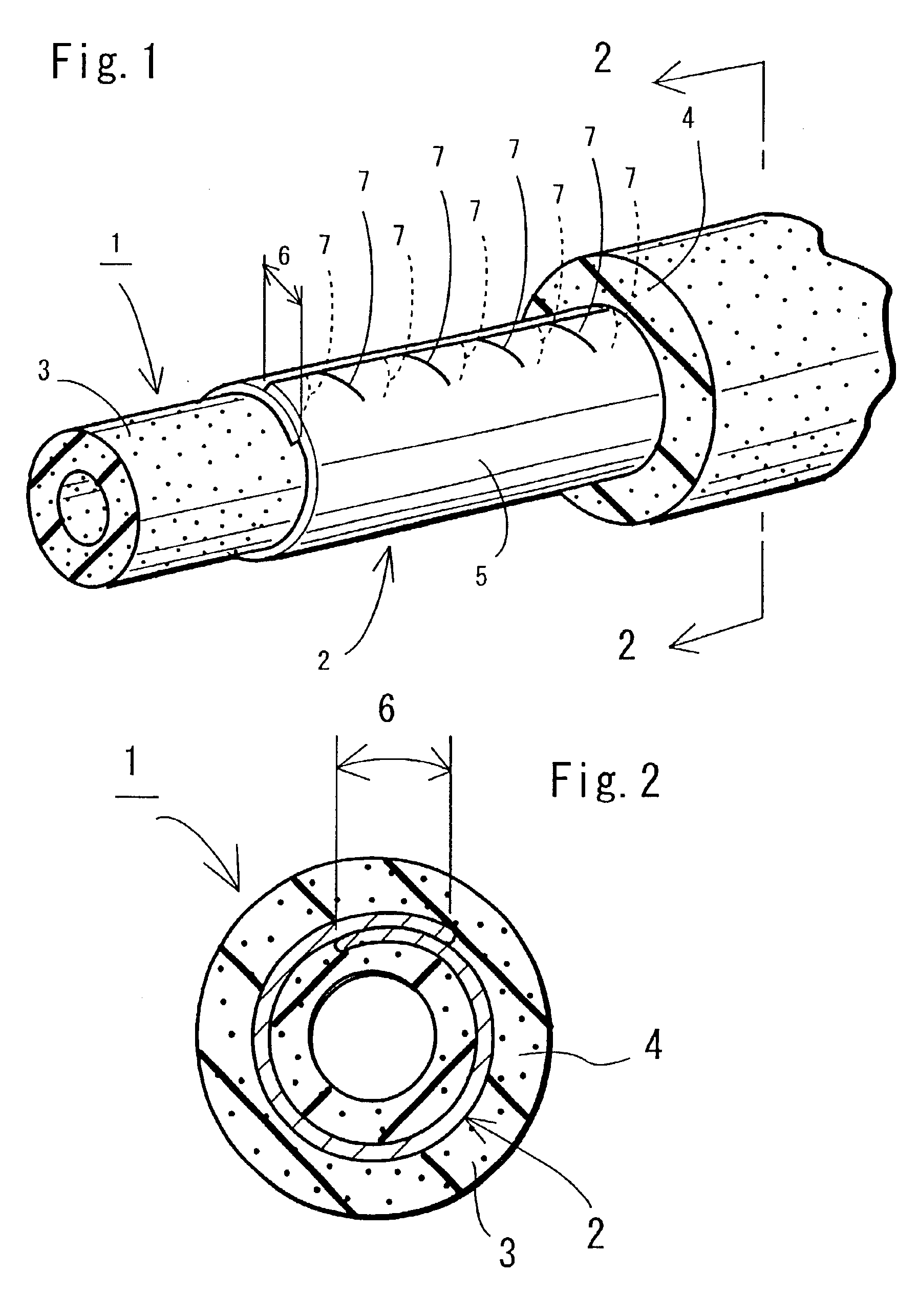
[0022]According to a thin rubber hose and its production method according to the present invention, when a resin film is rolled up in a cylindrical shape within an extrusion head or the like, because a weak section is provided in advance on the long sides, a strain in the resin film generated in the rolling-up process is adsorbed by deformation of the weak section. Because even a rigid resin film can be easily bent in the cylindrical shape, simultaneous extrusion molding is possible in a uniform shape. In addition, the degrees of freedom for bending at the time of vulcanizing molding can be increased. Further, sections other than an overlapping section of the film also closely contact the inner and outer layer rubbers by reduced pressure adsorption and this close contact can be maintained until completion of a vulcanizing process whereby the shape is finally determined. Accordingly, production of a thin hose that has been difficult until now is also possible. Further, it is possible to efficiently produce an impermeable rubber hose that is thin and has excellent pressure resistance.
[0040]Accordingly, when the thin rubber hose is mounted on the other member and secured by a spring clip, the fastening force becomes constant to improve the sealing properties, wherein it is possible to make it difficult for the rubber hose to become detached from the other member.

Problems solved by technology

When a liquid or gas transportation hose is thinned for the purpose of reducing weight and costs, an inner layer collapses in a process for weaving a reinforced intermediate layer and a process for coating a subsequent outer layer rubber according to a hose production method of conventional specifications and molding becomes very difficult.
Accordingly, if the intermediate layer film is made of a material which is soft and not flexible, a break or a twist is produced in the intermediate film layer and the method becomes limited, inasmuch as the film cannot be extrusion-molded into a uniformly cylindrical shape.
The above-mentioned problem is readily caused when the film is too hard to bend.
When the bending load (hereinafter simply referred to as “film bending load) of the film in measurements converted from bending modulus of the film material in the cross-section of which the width is 100 mm and the thickness is 0.05 mm is 400 N or more, it was difficult so far to perform extrusion-molding in a condition in which the film is rolled to allow the end sections to overlap.
It was also difficult to perform subsequent operations such as mounting of the hose on the mandrel.
However, it is difficult to satisfy the permeability resistance and a tear in the film is readily generated when used during molding or under high pressure.
However, when the film of such a thickness is a thermoplastic resin, because the resin strongly exhibits the properties of elasticity and rigidity as an inherent property, it is difficult to roll the film into a cylindrical shape so that it serves as an intermediate layer.
Accordingly, it is extremely difficult to mold vulcanized rubber hose by rolling up the film, which has a fixed thickness and a fixed hardness necessary to satisfy the permeability resistance and pressure resistance performance, to form an overlapping section, thereby performing simultaneous extrusion-molding.
Further, when the film is extrusion-molded in a condition in which volatile foreign material such as water is adhering to the surface of the film, the volatile content expands during a heating process such as vulcanizing.
Accordingly, there is some possibility that the product performance will deteriorate.

Method used


Image

  • Thin-walled rubber hose and method of producing the same
  • Thin-walled rubber hose and method of producing the same
  • Thin-walled rubber hose and method of producing the same

Examples


third embodiment

[0122]FIG. 13 is a third embodiment relating to a structure of the overlaping section. In FIG. 13A, lattice-shaped grooves 40 are provided on at least the overlapping section which are freely bendable. Irregularities such as embossment may be provided in place of the grooves 40. In FIG. 13B, wave-shaped irregularity consisting of recesses 41 and convex sections 42 extending in the vertical direction (in the longitudinal direction parallel to the long side sections) are provided. With this construction, the resin film 5 is easily bent at the recesses 41.

fourth embodiment

[0123]FIG. 14 shows a fourth embodiment relating to an overlapping section 6, in which rough surfaced sections 45 consisting of a minute recessed section or convex section, or of irregular sections are formed at an overlapping section of both end sections on the long sides using a surface roughening method. Since friction at the overlapping section 6 is increased by the rough surfaced sections 45, displacement is not easily caused. As the surface roughening method, there are a suitable mechanical method such as shot-blasting, a method for roughening a surface by chemical treatment and the like. The rough surfaced section is also allowed to be the weak section.

fifth embodiment

[0124]FIG. 15 is an end view of a resin film 5 which is formed in a cylindrical shape and FIG. 16 is an extended perspective view of the resin film 5. As is obvious from these figures, a metal film 50 is laminated to the resin film 5 to provide a laminated structure, wherein the metal film 50 is arranged to face inside. Both films are bonded at an overlapping section 6 by a suitable adhesive. However, if the metal film 50 is integrally embedded in the resin film 5, it is possible to integrally form the overlapping section 6 by welding.

[0125]Such a laminated structure can be provided in various manners, in which the resin film 5 can be a multilayered structure of from two layers to a maximum of about five layers. As a result of the multilayered structuring, characteristics of different resins can not only be compensated for, but also generation of pinholes in the resin film production process can be reduced. The entire thickness of the multilayered structure exhibits the same perfor...


PUM

PropertyMeasurementUnit
Forceaaaaaaaaaa
Widthaaaaaaaaaa
Widthaaaaaaaaaa

Abstract

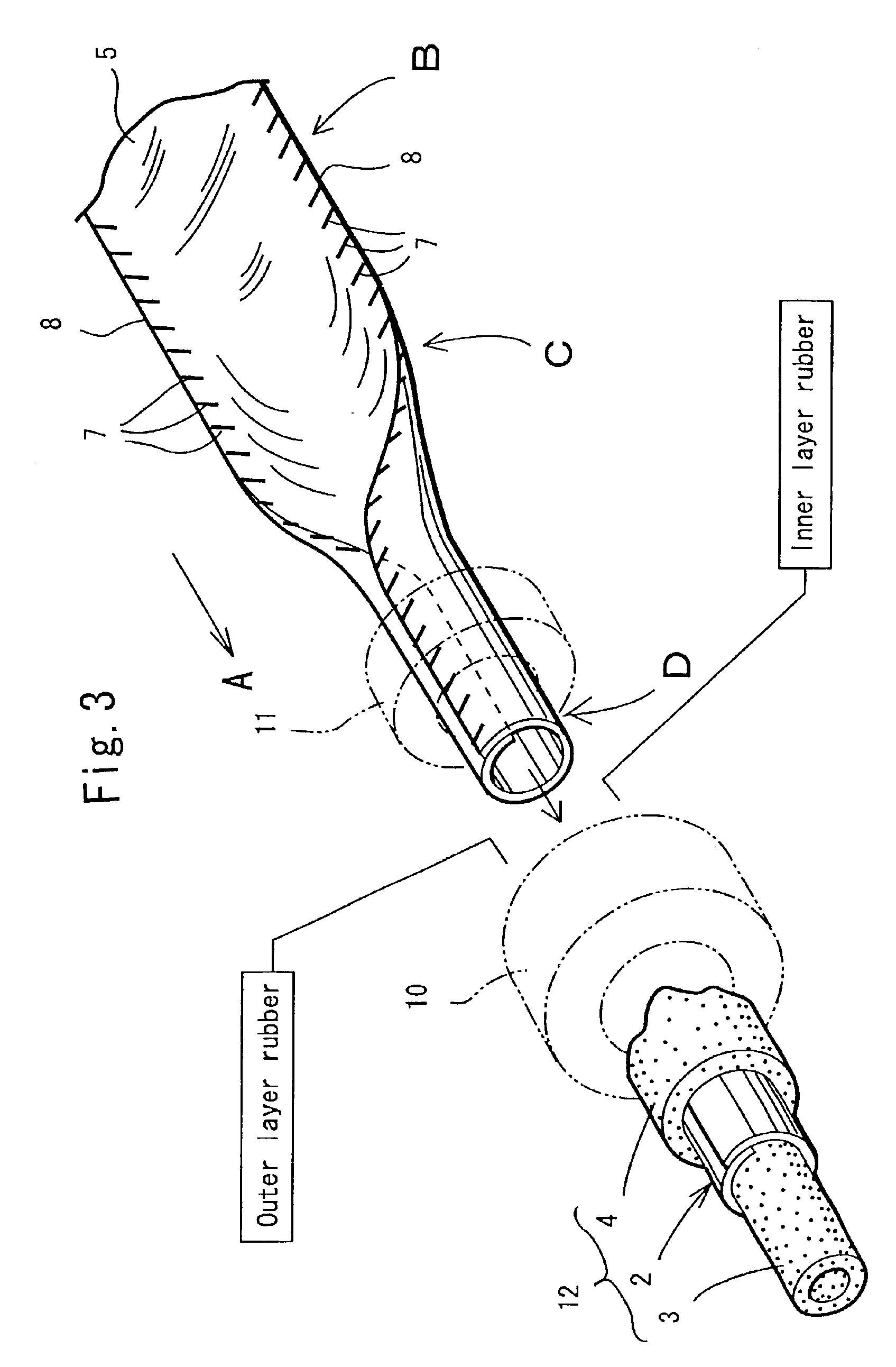
An impermeable rubber hose is thinned for the purpose of reducing weight and costs. A rigid resin film is used as an intermediate layer. When the resin film is gradually rolled up into a cylindrical shape from a planar shape and fed to an extrusion head and rubber is simultaneously extrusion-molded inside and outside the cylindrical film, the film produces a break or a twist to make extrusion molding difficult. It is an object of the present invention to make simultaneous extrusion molding possible even in such a condition.To attain the above object, a thermoplastic resin film (5) which forms an intermediate layer (2) and of which the melting point is lower than the vulcanizing temperature is formed in a long belt-shape. Slits (7) are provided at fixed intervals on the right and left long side sections (8, 8) of the film (5) in the longitudinal direction. When the resin film (5) is fed into an extrusion head (10) to be rolled up into a cylindrical shape, because both the long side sections (8, 8) of the film (5) are formed as weak sections by the slits (7), the film (5) adsorbs a strain when bent and is bent in a circle, thereby allowing the right and left long side sections (8, 8) to overlap at an overlapping section (6). In this condition, rubber is simultaneously extrusion-molded inside and outside the film and then, vulcanized to weld the overlapping section (6), thereby eliminating the slits (7).

Description

[0001]This application is the national phase under 35 U.S.C. § 371 of PCT International Application No. PCT / JP01 / 05129 which has an International filing date of Jun. 15, 2001, which designated the United States of America.FIELD OF THE INVENTION[0002]The present invention relates to a method for producing a liquid or gas transportation hose, and more particularly to a method for extrusion-molding rubber inside and outside an intermediate layer which is formed by rolling up a film made of a resin or the like into a cylindrical shape to allow both ends in the bending direction to overlap.DESCRIPTION OF THE PRIOR ART[0003]An example of a rubber hose wherein rubber and a resin film are laminated is disclosed in Japanese Unexamined Patent Publication No. SHO 60-113882 in which an inner layer rubber, the resin film serving as an intermediate layer, and an outer layer rubber are extrusion-molded one by one. Also, in Japanese Unexamined Patent Publication No. HEI 7-314610, there is a descrip...

Claims


Application Information

Patent Timeline
IPC IPC(8): B29C47/20B29C47/28B29C47/02F16L11/04F16L11/06F16L11/08B29C48/09B29C48/34
CPCB29C47/0016B29C47/023B29C47/28F16L11/04F16L11/06F16L2011/047Y10S138/10B29C48/06B29C48/153B29C48/34B29C48/09
Inventor BABA, HIROKIHIRANO, YUJIFUJII, HIROMIMATANO, TAKAFUMI
Owner YAMASHITA RUBBER CO LTD
Learn More