
Apparatus and method for fast arc extinction with early shunting of arc current in plasma

a plasma and arc current technology, applied in plasma welding apparatus, plasma technique, manufacturing tools, etc., can solve the problems of high power density, high loss in cable and power supply, so as to reduce the effect of arcing and reduce the probability of micro arcs

Inactive Publication Date: 2005-09-13
ADVANCED ENERGY IND INC
View PDF14 Cites 92 Cited by
  • Summary
  • Abstract
  • Description
  • Claims
  • Application Information

AI Technical Summary

Benefits of technology

[0015]There is provided by this invention a power supply for dc based plasma processes that reduces the effects of arcing in the process by minimizing the current delivered to the arc, and by utilizing a shunt switch to divert current away from the plasma early in the arc initiation process, thus substantially decreasing the probability that a micro arc will develop into a hard arc. After a predetermined short time interval following the actuation of the shunt switch, the power supply turns off the shunt switch and checks to see if the output voltage rises. If the output voltage does rise, the shunt switch remains off, and normal operation resumes. If the output voltage remains low, the shunt switch is turned on again to allow further time for the arc to become extinguished.

Problems solved by technology

The plasma is then discharged through this hard arc, creating a very high density of power that can, if not extinguished quickly, be very detrimental to the process and the quality of the film.
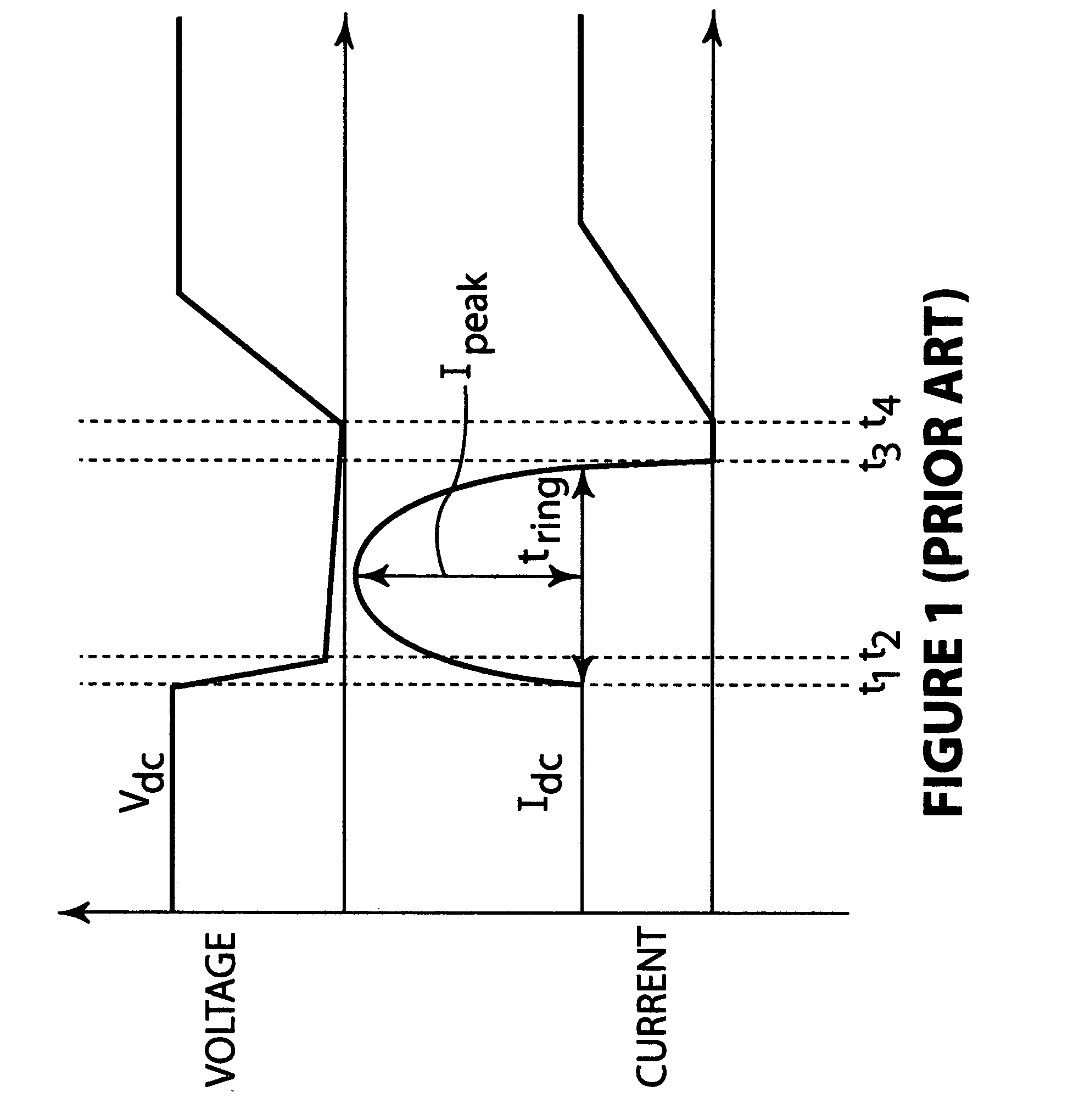
After the power supply turns off, the energy stored in the cable is dissipated into the arc and losses in the cable and power supply.
Passive ring out circuits produce large overshoots in the output current, and depending on the values of the resonant components, this may result in large amounts of energy being dumped into the process.
Having too large of a reverse voltage can be detrimental if a reverse current flows after the arc, so extra circuitry to prevent reverse currents may sometimes be required, as is taught in U.S. Pat. No. 6,645,698 and U.S. Pat. No. 6,524,455.

Method used


Image

  • Apparatus and method for fast arc extinction with early shunting of arc current in plasma
  • Apparatus and method for fast arc extinction with early shunting of arc current in plasma
  • Apparatus and method for fast arc extinction with early shunting of arc current in plasma

Examples


Embodiment Construction

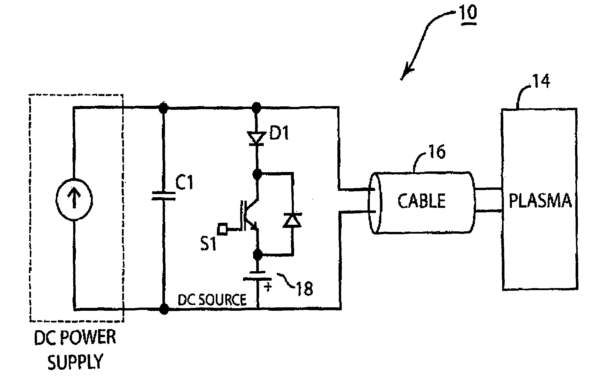
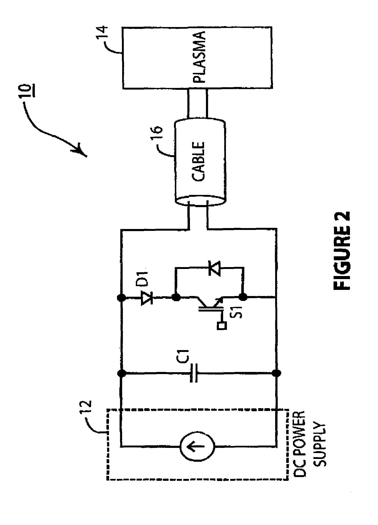
[0021]Referring to FIG. 2 there is shown a dc plasma processing apparatus 10 that incorporates the principles of this invention. A dc power supply 12 supplies power to plasma 14 via a cable 16. The plasma 14 is ignited between electrodes (not shown), and is contained in a chamber (not shown) for processing a work piece on a substrate also not shown but well known to those skilled in the art. Connected in parallel with the output capacitor C1 is a shunt switch S1. The shunt switch may be an insulated-gate bipolar transistor (IGBT), field effect transistor (FET), or other suitable semiconductor switch.

[0022]The dc power supply should be designed to be a compliant current source on the time scale of the arc so that its output current will not rise very much when the output voltage is decreased when arcs occur. The typical way do achieve high compliance in the dc power supply is to have either a sufficiently large inductance in series with the output, or have a fast current programmed c...


PUM

PropertyMeasurementUnit
Timeaaaaaaaaaa
Timeaaaaaaaaaa
Currentaaaaaaaaaa

Abstract

There is provided by this invention a novel apparatus and method of operating a dc plasma process that diverts the power supply current from the plasma at the initiation of an arc, thereby inhibiting energy from flowing from the power supply to the plasma, and then to allow energy to flow again when the power supply re-enables energy flow to the plasma. The diverting means is connected to the output of the power supply to divert current away from the plasma at the initiation of an arc wherein the diverting means is actuated when the arc is detected on the output and diverts the current for a first pre-determined time. The diverting means is released at the end of the first pre-determined time before the current reaches zero wherein current is redirected to the plasma and the diverting means is reactivated at the end of a second pre-determined time in the event the arc is not extinguished.

Description

BACKGROUND OF THE INVENTION[0001]1. Field of the Invention[0002]This invention relates generally to power supplies that detect and prevent or extinguish arcs in plasma processing applications, and more particularly to dc processes and apparatus and methods to extinguish arcs therein.[0003]2. Brief Description of the Prior Art[0004]A cathodic arc is said to develop in a plasma-based process when a discharge occurs between a point on an insulator where charge has accumulated and a point on the cathode. The impedance of the plasma then collapses and this is often termed a micro arc. In the past, these micro arcs were often ignored as not important. Oftentimes their very existence went undetected, since the power supply did not detect their existence directly. If a micro arc does not extinguish fast enough, there can be a cascading effect where the micro arc develops into what is termed as a hard arc. The plasma is then discharged through this hard arc, creating a very high density of p...

Claims


Application Information

Patent Timeline
IPC IPC(8): B23K9/00
CPCB23K10/006H01J37/32935H05H1/36H01J2237/0206H01J37/32944
Inventor ILIC, MILANSIDDABATTULA, KALYAN N. C.MALININ, ANDREY B.
Owner ADVANCED ENERGY IND INC
Learn More