Eureka AIR delivers breakthrough ideas for toughest innovation challenges, trusted by R&D personnel around the world.

Portable air heating system

a heating system and air technology, applied in the field of portable air heating systems, can solve the problems of limited value of heat packets, people in remote areas are often subject to extreme temperature variations, and experience much lower temperatures, and achieve the effects of reliable, efficient and safe heat supply, and convenient assembly and disassembly

Inactive Publication Date: 2005-09-13
TAPS
View PDF12 Cites 13 Cited by
  • Summary
  • Abstract
  • Description
  • Claims
  • Application Information

AI Technical Summary

Benefits of technology

[0011]In accordance with the present invention, as embodied and broadly described herein, the foregoing needs are met by a portable air heating system. The portable air heating system is particularly useful in remote areas where access to more conventional methods for providing heat are unavailable, though the heating system may also be utilized in a variety of other locations as well. Advantageously, the air heated by the heating system is isolated from combustion-produced exhaust gases, allowing the air within an enclosed space, such as a tent, to be heated safely.
[0013]Another aspect of the portable air heating system is the heat transfer housing which includes one or more exterior walls defining the perimeter of the housing, and a plurality of passages or heat transfer tubes extending from one side of the housing to the other side of the housing. The heat transfer tubes, which transport the air to be heated through the heat transfer housing, advantageously isolate the air to be heated from the harmful exhaust gases produced by burning fuel during operation of the air heating system. Additionally, the heat transfer tubes may be constructed of copper, and are arranged in a pattern that maximizes their exposure to heat produced by a burner during operation of the air heating system. Thus, the heat transfer tubes are configured to absorb the heat produced by the burner and transfer it to the air flowing through the heat transfer tubes. The heat transfer housing preferably includes one or more heat deflectors that assist in directing the heat produced by the burner toward the heat transfer tubes. The heat deflectors also increase the safety of the system by reflecting the heat away from the exterior walls of the heat transfer housing so that the walls are not the primary point of heat contact.
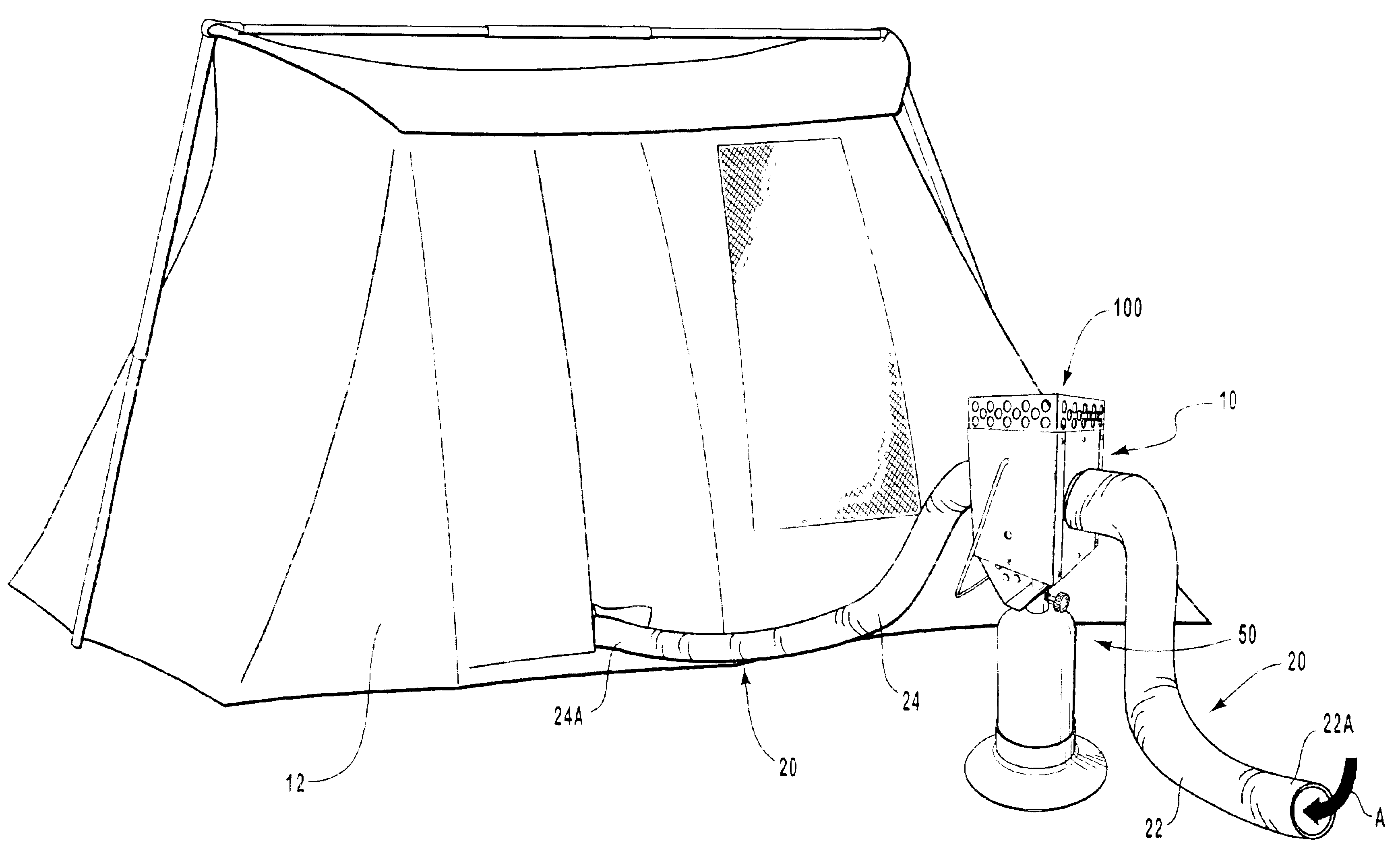
[0015]To operate the portable air heating system, the system is first securely placed on the ground or other stable location outside the structure to be heated, such as a tent. The free end of the air intake conduit is also placed outside the structure to be heated, where it has access to fresh, ambient air. Alternatively, the free end of the air intake conduit may be positioned inside the structure to be heated to recirculate air from inside the structure through the heat transfer housing circulate. Recirculating the air inside the structure allows the structure to be heated more quickly and to a higher temperature. The free end of the air outlet conduit is disposed within the structure to supply heated air to the structure.
[0017]The air flowing through the air transfer assembly does not mix with the exhaust gases. That is, the heated air at no point comes into contact with the potentially dangerous gases, such as carbon monoxide, produced as a byproduct of the fuel combustion. These exhaust gases, which are produced in the heat transfer housing located exterior to the tent, pass harmlessly out of the heat transfer housing and into the atmosphere during operation of the heating system. Thus, the tent or other structure is safely isolated from the harmful exhaust gases, thereby safely heating the interior of the structure to provide a comfortable environment for persons therein.
[0019]In addition to safely heating enclosed areas or one's person, the portable air heating system is also compact and portable, thereby allowing it to be easily transported to remote areas. Due to its simple design, the system is also easily set up for use in a minimum amount of time.

Problems solved by technology

Without the benefit of temperature-regulated buildings or structures, a person in a remote area is often subject to extreme temperature variations.
Yet, because of their high elevation, these areas often experience much lower temperatures than are comfortable, especially at night.
Despite their convenience, such heat packets are of limited value because of their small size and limited output of heat.
Also, these packets cannot heat an enclosed space, such as the interior of a structure like a tent, tent trailer, camper or camp trailer.
Notwithstanding their ability to heat an enclosed interior space, direct air combustion heaters can pose serious safety hazards.
This reaction also creates a byproduct of potentially dangerous gases, such as carbon monoxide and carbon dioxide.
These exhaust gases are potentially very dangerous and in some cases deadly because they may replace the oxygen within an enclosed environment, such as a tent, tent trailer, camper, or camp trailer, and potentially asphyxiate or at least make the persons therein ill.
Additionally, placing direct air combustion heaters inside the tent or camp trailer poses a fire hazard due to the flammable materials often stored inside such structures, or from which such structures are manufactured.

Method used


Image

  • Portable air heating system
  • Portable air heating system
  • Portable air heating system

Examples


Embodiment Construction

[0033]Reference will now be made to the figures where various structures will be provided with reference number designations. It is understood that the drawings are diagrammatic and schematic representations of possible embodiments of the invention, and are not intended to limit the scope of the present invention nor are they necessarily drawn to scale. Further, one skilled in the art will appreciate that terms such as top, bottom, upper, and lower as used herein are merely words used to describe the accompanying figures, and are not meant to limit the scope of the present invention in any way.

[0034]FIGS. 1-9 depict various elements of a self-contained, portable air heating system. Advantageously, the inventive portable heating system provides a reliable source of heated air to an enclosed structure, such as a tent or camp trailer, while eliminating the introduction of potentially dangerous exhaust gases, such as carbon monoxide, into the enclosed structure. In addition, the air hea...


PUM


Abstract

A portable air heating system for use in remote areas is disclosed. The portable air heating system provides a stream heated air for use in heating the interior of a structure, such as a tent or camp trailer. The heating system generally comprises an air transfer assembly for providing a flow of air through the system, a fuel burner assembly for providing heat by combustion, and a heat transfer housing for safely transferring the heat produced by the fuel burner assembly to the air flowing through the transfer assembly. The burner assembly and the heat transfer housing are both positioned outside the area being heated. Further, the exhaust gases are completely isolated from the air heated by the system, thereby virtually eliminating the likelihood of asphyxiation by the exhaust gases from the burner. The present heating system is also highly portable and simple to use, thereby providing an efficient mechanism for providing heat where more traditional heating apparatus are not readily available.

Description

CROSS-REFERENCE TO RELATED APPLICATIONS[0001]This application claims the benefit of U.S. Provisional Application No. 60 / 311,647, filed Aug. 10, 2001 and entitled “Portable Air Heating System,” which is hereby incorporated by reference.BACKGROUND OF THE INVENTION[0002]1. Field of the Invention[0003]The present invention generally relates to heating devices. More particularly, the present invention relates to a portable air heating system for use in remote areas.[0004]2. Description of Related Art[0005]The popularity of outdoor recreation in the United States has grown tremendously in recent years. An ever increasing number of outdoor activities have become more accessible to a greater number of people, resulting in a greater proportion of the general population spending more time in less developed and remote areas of the country. Examples of such recreational activities include hiking, biking, camping, hunting, rock climbing, and mountain climbing.[0006]This increased interest and pa...

Claims


Application Information

Patent Timeline
Patent Type & Authority Patents(United States)
IPC IPC(8): F24H3/02F24H3/08F24H1/06
CPCF24H1/06F24H3/087E04H15/12
Inventor ADRIAN, TREVOR
Owner TAPS
Why Eureka
Eureka Blog
Learn More