Bandpass predistortion method and apparatus for radio transmission

Active Publication Date: 2005-09-06
NORTHROP GRUMMAN SYST CORP
View PDF11 Cites 1 Cited by
  • Summary
  • Abstract
  • Description
  • Claims
  • Application Information

AI Technical Summary

Benefits of technology

[0005]The present invention is an apparatus for and a method of amplitude and phase distorting a modulated radio frequency signal such that after passing of the distorted signal through a non-linear power amplifier, undesirable spurious emissions in the resulting spectrum are reduced. In accordance with the present invention, a complex amplitude modulated baseband signal, having an in-phase component I and a quadrature component Q, is sampled to obtain k samples Ik of the in-phase component and k samples Qk of the quadrature component, and the magnitude of the envelope of the baseband samples is determined. A distortion factor based on the product of the hyperbolic tangent (“tanh”) and the inverse hyperbolic tangent or archyperbolic tangent (“atanh”) of a scaled value of the complex baseband sample magnitude is used to multiply each sample of the in-phase component and of the quadrature component so as to provide predistorted components. These predistorted components are combined and used to provide a distorted radio frequency (“RF”) signal which is applied to the power amplifier. The power amplifier distortion cancels the distortion in the radio frequency signal so that the power amplifier provides a substantially undistorted output signal.
[0007]The envelope of the baseband signal is thus subjected to amplitude and phase predistortion prior to upconversion to the radio frequency signal. This avoids impressing pick-up noise on the transmitted envelope. It is possible to do the predistortion prior to intermediate frequency (IF) and RF bandpass filtering of the radio frequency signal since such filtering has a wide bandwidth, allowing the distorted signal spectrum to pass through the power amplifier.

Problems solved by technology

The power amplifier distortion cancels the distortion in the radio frequency signal so that the power amplifier provides a substantially undistorted output signal.

Method used


Image

  • Bandpass predistortion method and apparatus for radio transmission
  • Bandpass predistortion method and apparatus for radio transmission
  • Bandpass predistortion method and apparatus for radio transmission

Examples


Embodiment Construction

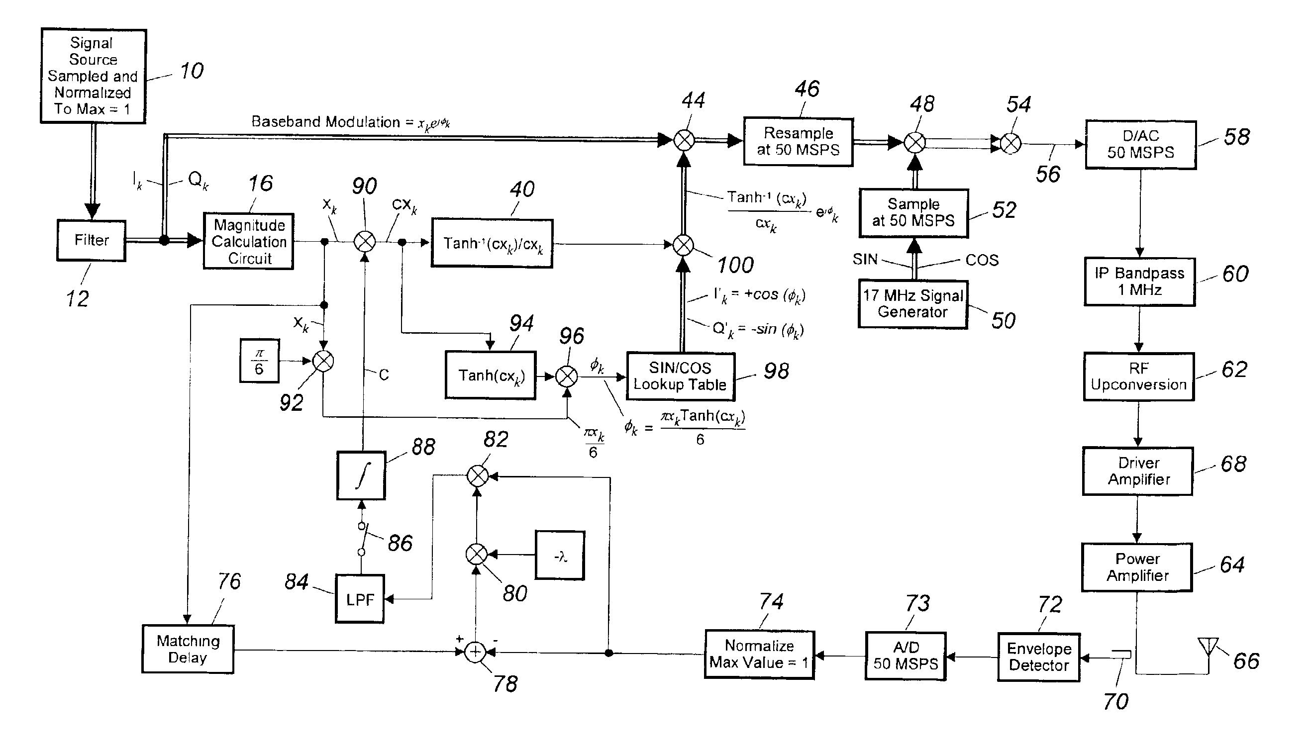
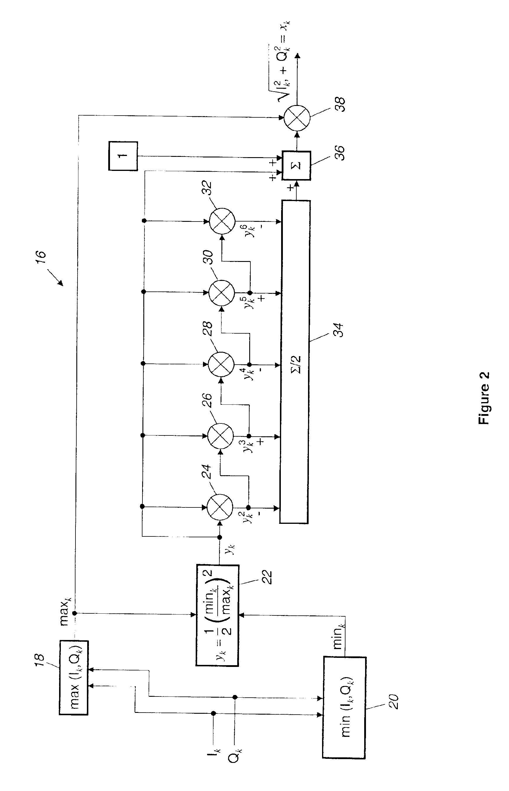
[0015]FIG. 1 depicts an apparatus for generating an amplitude and phase predistorted radio frequency signal in accordance with a preferred embodiment of the present invention. A signal source 10 provides a complex baseband signal xejφk, where x is the envelope of the signal and, for example, may be an Edge GSM or a D8PSK signal. The signal includes an in-phase component I and a quadrature component Q that are normalized and sampled at, for example, 10.5 kilosamples per second (KSPS). From source 10, the samples are filtered in filter circuit 12 to produce smooth transitions between phase symbols. The samples Ik of the in-phase component and the samples Qk of the quadrature component are applied from filter circuit 12 to a calculation circuit 16 which calculates the magnitude of the scaled complex baseband envelope sample, for example by determining the square root of the sum of the squares of the scaled in-phase component sample and the scaled quadrature component sample.

[0016]FIG. ...


PUM


Abstract

An apparatus and method for generating an envelope predistorted radio frequency signal which avoids undesirable spurious emissions. A complex baseband signal, having an in-phase component I and a quadrature component Q, is sampled and filtered in a sampling circuit and filter circuit to obtain samples Ik of the in-phase component and samples Qk, the quadrature component. The magnitude xk of each sample pair is determined in a first calculation circuit. An amplitude and phase distortion factor Dk, based on scaled values of the archyperbolic tangent and the hyperbolic tangent of the baseband sample magnitude is determined in further calculation circuit and a multiplier. Each sample Ik of the in-phase component and Qk of the quadrature component is multiplied by the corresponding distortion factor Dk, and the resulting predistorted components combined and upconverted to provide a predistorted baseband signal which is amplified in a power amplifier having hyperbolic tangent distortion.

Description

CROSS-REFERENCE TO RELATED APPLICATION[0001]This application is related to U.S. patent application Ser. No. 09 / 624,149 filed Jul. 24, 2000.FIELD OF THE INVENTION[0002]The present invention pertains to an apparatus for and a method of applying both amplitude predistortion and phase predistortion to a modulated baseband signal. More particularly, the present invention pertains to an apparatus for and a method of generating an amplitude modulated radio frequency signal by amplitude predistorting its baseband signal, using the inverse hyperbolic tangent of a value based on the envelope of the baseband in-phase and quadrature components, and phase predistorting the baseband signal, using the hyperbolic tangent of that value.BACKGROUND OF THE INVENTION[0003]Environments such as commercial airliners frequently have several radios that operate at different frequencies. Not only must these radios avoid interference with each other, but also they must meet spectrum mask requirements imposed b...

Claims


Application Information

Patent Timeline
IPC IPC(8): H04L27/34H04L27/36
CPCH03F1/3247H03F1/3282H04L27/368H03F2200/336H03F2201/3233
Inventor MYERS, MICHAEL H.
Owner NORTHROP GRUMMAN SYST CORP
Why Eureka
Try Eureka