
Methods and apparatus for making color filter by discharging a filter material

a filter material and filter material technology, applied in the direction of identification means, inking apparatus, instruments, etc., can solve the problems of efficient consumption of raw materials and complex processes such as those employing photolithography techniques

Inactive Publication Date: 2005-09-06
KATEEVA
View PDF29 Cites 18 Cited by
  • Summary
  • Abstract
  • Description
  • Claims
  • Application Information

AI Technical Summary

Benefits of technology

[0015]Accordingly, it is a feature of the present invention to provide a method and an apparatus for manufacturing an optical component which can make uniform the planar optical characteristics of the optical component, i.e., the light transmission characteristics of a color filter, the color display characteristics of a liquid crystal device, the light-emission characteristics of an electro-luminescent surface.
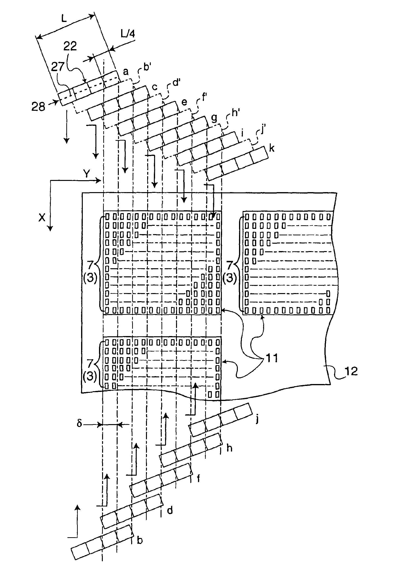
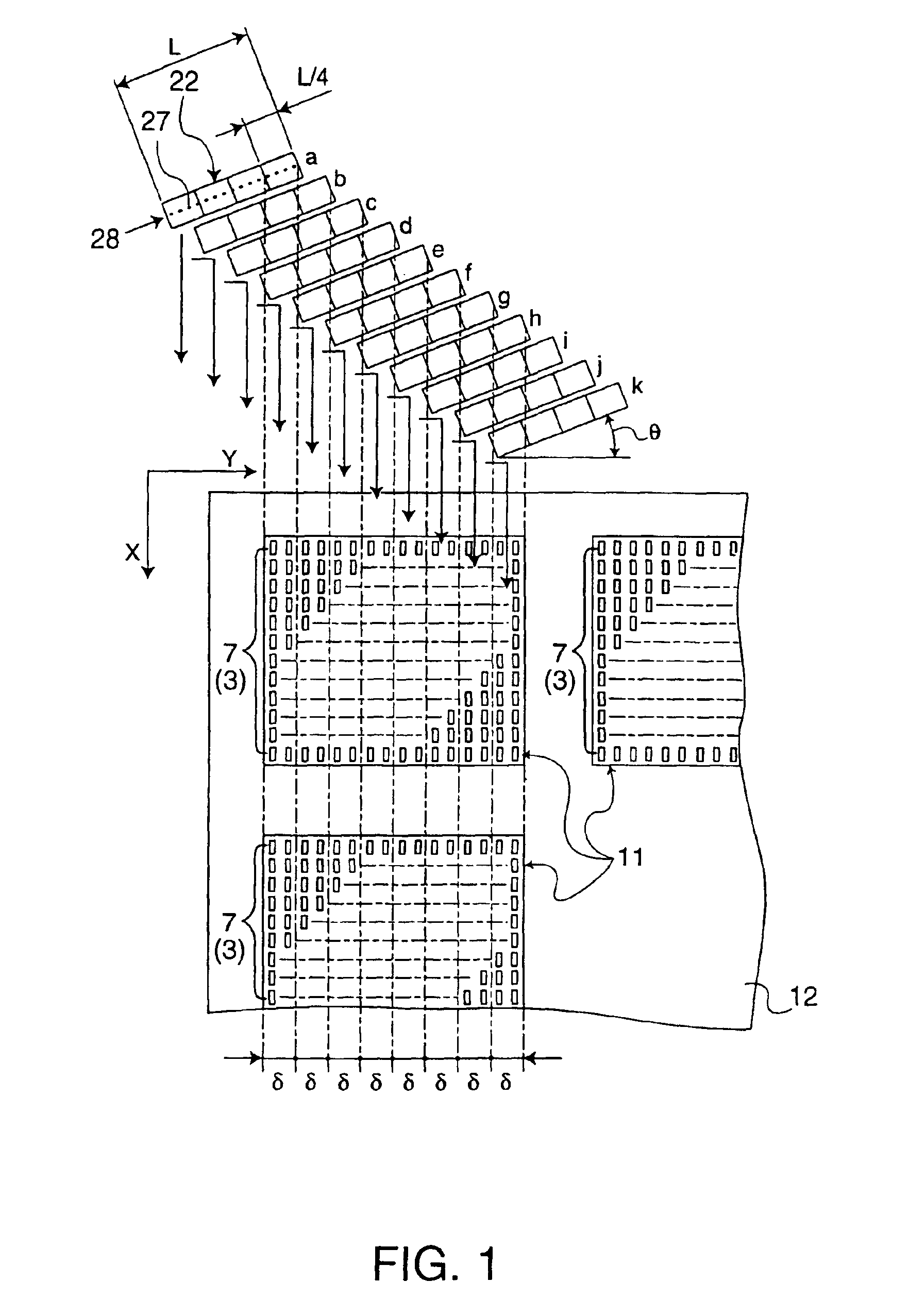
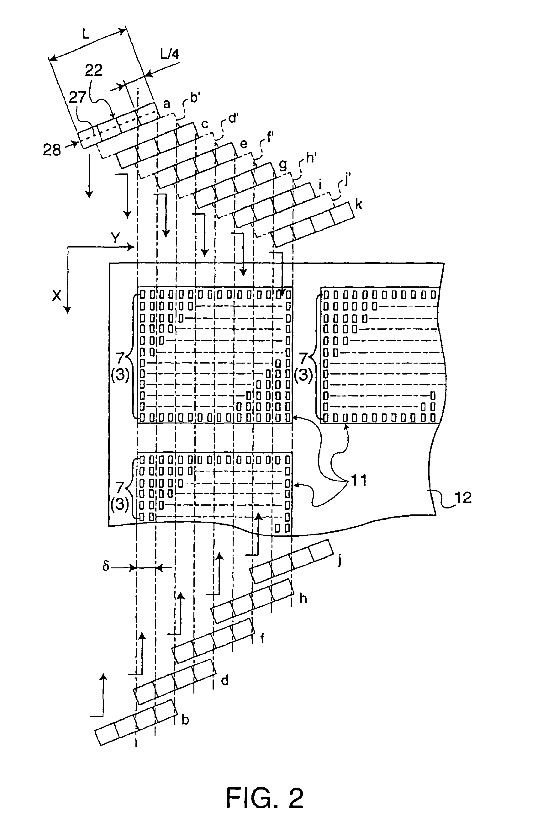
[0016]In achieving these features, the present invention provides a method for making a color filter with a plurality of filter elements aligned on a substrate. The method can include a step of moving one of a inkjet head and the substrate in a first-scanning direction relative to the other, wherein the inkjet head has a nozzle line including a plurality of nozzle groups each including a plurality of nozzles, a step of selectively discharging a filter material from the plurality of nozzles to form the plurality of filter elements, and a step of moving one of the inkjet head and the substrate in a second-scanning direction relative to the other so that at least a part of each nozzle group is capable of scanning the same section of the substrate in the first direction.
[0017]In accordance with the above-described method for making the color filter, each of the filter elements in the color filter is not formed by one first-scanning of the inkjet head, but instead each of the filter elements is formed into a predetermined thickness by being applied with ink n times from the plurality of nozzles belonging to different nozzle groups. Accordingly, even when there is a variation between the discharged amounts of ink among the plurality of nozzles, variations in the layer thickness among the plurality of filter elements can be avoided, and light transmission characteristics of the color filter can thereby be made uniform.
[0018]It is apparent that because the filter elements are formed by discharging ink from the inkjet head in the above-described method, complex processes such as those employing photolithography techniques are not required and the raw materials are efficiently consumed.

Problems solved by technology

It is apparent that because the filter elements are formed by discharging ink from the inkjet head in the above-described method, complex processes such as those employing photolithography techniques are not required and the raw materials are efficiently consumed.

Method used


Image

  • Methods and apparatus for making color filter by discharging a filter material
  • Methods and apparatus for making color filter by discharging a filter material
  • Methods and apparatus for making color filter by discharging a filter material

Examples


Embodiment Construction

[0057]An embodiment of a manufacturing method and a manufacturing apparatus for a color filter will now be described. First, before describing this method and apparatus, a color filter manufactured by this method and apparatus is explained. FIG. 5A is a plan view of the structure of a color filter according to one embodiment. FIG. 6D shows a cross-section of the structure cut along line VI—VI in FIG. 5A.

[0058]A color filter 1 of this embodiment can be made by forming a plurality of filter elements 3 on the surface of a rectangular substrate 2 composed of glass, plastic, or the like, the plurality of filter elements 3 being arranged in a dot-pattern, i.e., dot-matrix pattern in this embodiment, and depositing an overcoat 4 thereon as shown in FIG. 6D. Note that FIG. 5A is a plan view of the color filter 1 without the overcoat 4.

[0059]Each of the filter elements 3 can be formed by filling one of the rectangular regions which are aligned in a dot-matrix pattern and are separated from o...


PUM

PropertyMeasurementUnit
sizeaaaaaaaaaa
temperatureaaaaaaaaaa
thicknessaaaaaaaaaa

Abstract

The present invention provides a method for making a color filter having a plurality of filter elements aligned in a dot-matrix on a substrate. The method has a first-scanning step of moving the inkjet head having a nozzle line including a plurality of nozzles relative to the substrate while selectively discharging a filter material from the plurality of nozzles so as to form filter elements on filter element forming regions of the substrate and a second-scanning step of moving the inkjet head by a second-scanning distance δ in a second-scanning direction. The plurality of nozzles are divided into a plurality of groups and the first-scanning step and the second-scanning step are repeated so that all the nozzle groups scan the same section of the substrate.

Description

[0001]This is a Divisional of application Ser. No. 09 / 988,743, filed Nov. 20, 2001 now U.S. Pat. No. 6,660,332. The entire disclosure of the prior application is hereby incorporated by reference herein in its entirety.BACKGROUND OF THE INVENTION[0002]1. Field of Invention[0003]The present invention relates to a method and an apparatus for making a color filter used in an optical device, such as a liquid crystal display. The present invention also relates to a method and an apparatus for making a liquid crystal display having a color filter. Furthermore, the present invention relates to a method and an apparatus for making an electro-luminescent (EL) device for display using an electro-luminescent layer.[0004]Also, the present invention relates to a method for discharging a material, and an apparatus for discharging thereof. Further, the present invention relates to electronic apparatus with a liquid crystal display device or an electro-luminescent device manufactured by the methods....

Claims


Application Information

Patent Timeline
Patent Type & Authority Patents(United States)
IPC IPC(8): B41J2/15B41J2/21B41J2/145B41J2/01G02B5/20G02F1/1335G09F9/30G09F9/35H01L27/32H01L51/50H05B33/10H05B33/12
CPCB41J2/15B41J2/2132G02B5/201B41J2202/09G02B5/20
Inventor KAWASE, TOMOMIARUGA, HISASHIKATAGAMI, SATORUSHIMIZU, MASAHARUKIGUCHI, HIROSHI
Owner KATEEVA
Learn More