
Neck cleaning method for a CRT

a cleaning method and cathode ray tube technology, applied in the manufacture of spark plugs, electrode systems, electric discharge tubes/lamps, etc., can solve the problems of squeegee wear during use, streaks of coating material within the neck, and the inability of the coating to extend along the entire neck of the tub

Inactive Publication Date: 2005-09-06
THOMSON LICENSING SA
View PDF1 Cites 0 Cited by
  • Summary
  • Abstract
  • Description
  • Claims
  • Application Information

AI Technical Summary

Benefits of technology

[0007]A method of cleaning the neck of a funnel of a CRT during the manufacture thereof. The method comprises: inserting a drain tube within the neck, wherein the outer dimensions of the drain tube are less than the corresponding inner dimensio

Problems solved by technology

However, to create an operational CRT, the coating cannot extend along the entire neck of the tube.
The problem with this system is that the squeegee wears during use and will ultimately leave streaks of coating material within the neck.

Method used


Image

  • Neck cleaning method for a CRT
  • Neck cleaning method for a CRT
  • Neck cleaning method for a CRT

Examples


Embodiment Construction

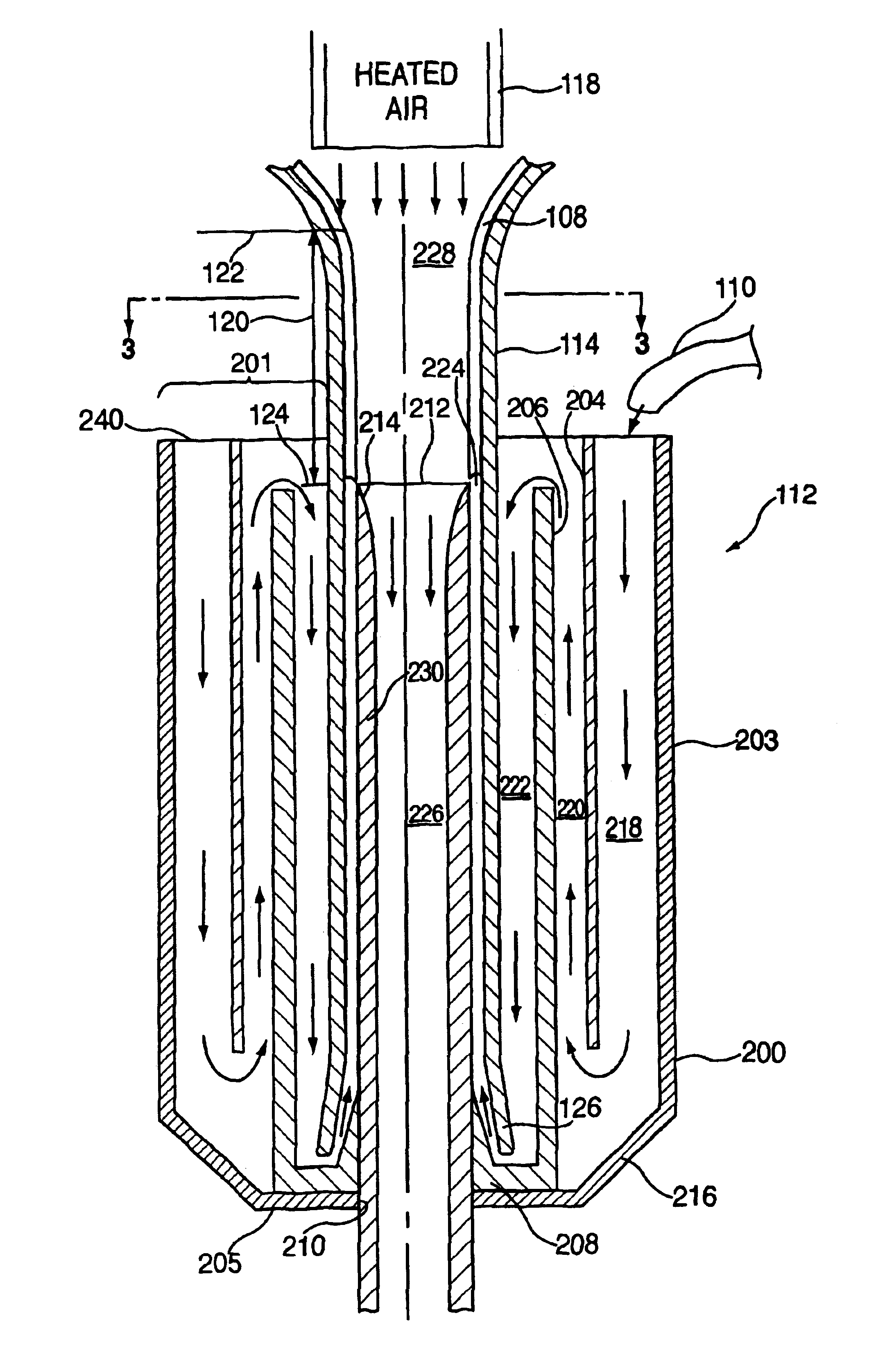
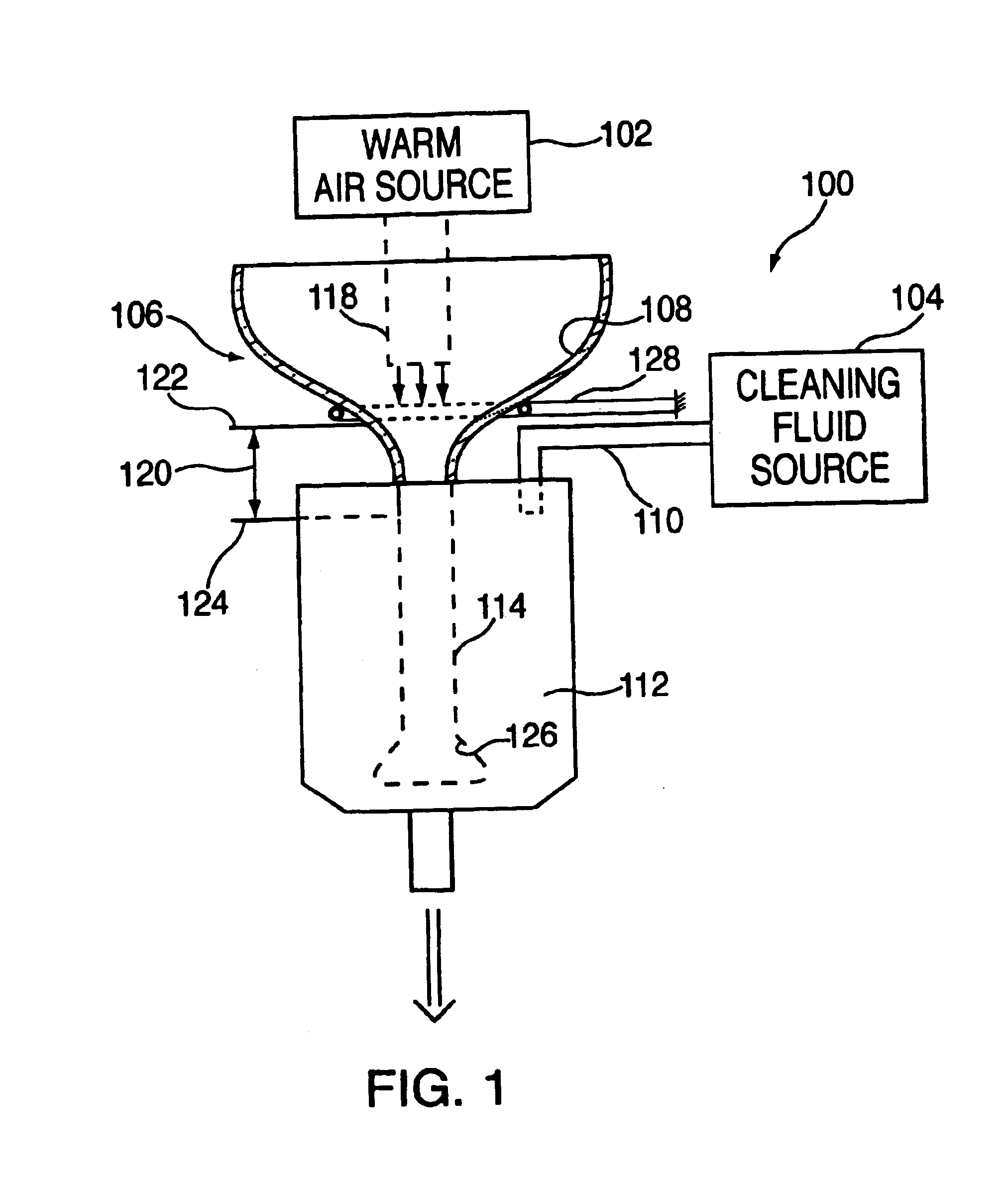
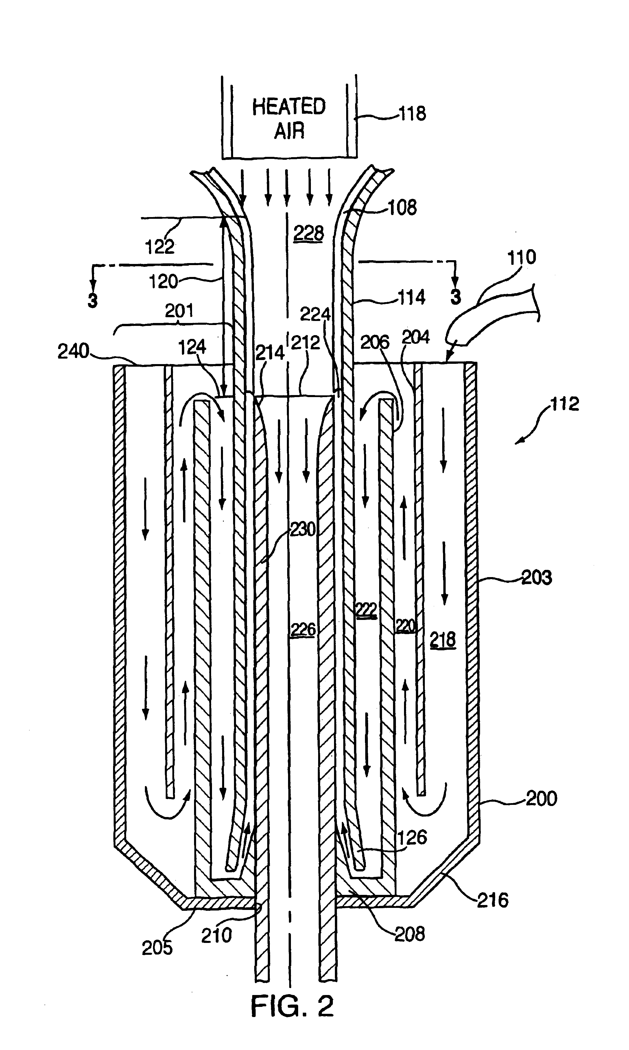
[0013]FIG. 1 depicts a schematic view of the apparatus for cleaning the neck of a tube of a CRT in accordance with the present invention. The apparatus 100 comprises a warm air source 102, a mechanism 128 for supporting the funnel 106, a cleaning fluid source 104, and a cleaning unit 112. Prior to being mounted in support mechanism 128, the funnel 106 is heated to between 50 and 55° C. before being coated with a layer 108 of graphite, iron oxide or other conductive material, along the entire inner surface of the funnel 106 and the neck 114 of the funnel 106. The coating process is conventional and well known in the art.

[0014]Once coated, the funnel 106 is mounted in the support mechanism 128 before the coating has time to fully cure. The support mechanism 128 generally supports the funnel 106 above the cleaning unit 112. Since the layer of coating material is not completely cured, the coating material can be removed using a non-caustic cleaning agent such as de-ionized water. The su...


PUM

PropertyMeasurementUnit
Flow rateaaaaaaaaaa
Dimensionaaaaaaaaaa

Abstract

A method of cleaning the neck of a funnel of a CRT during the manufacture thereof. The method includes: inserting a drain tube within the neck, wherein a gap exists between the drain tube and the neck; directing a fluid through the gap; and draining the fluid that was directed through the gap through the drain tube, whereby the fluid removes material from the neck that was applied during a prior coating process and any dirt. The drain tube is part of a cleaning apparatus that further includes a housing and a labyrinth flow controller positioned within the housing adjacent to the drain tube forming a laminar flow section whereby fluid is directed through the housing and into the tube.

Description

CROSS-REFERENCE TO RELATED APPLICATIONS[0001]This application is a divisional of U. S. patent application Ser. No. 09 / 997,661 U.S. Pat. 6,669,525 entitled “Neck Cleaning Method For A CRT” filed on Nov. 29, 2001 issued Dec. 30, 2003.FIELD OF THE INVENTION[0002]The present invention generally relates to the manufacture of cathode ray tubes and, in particular, to a method of cleaning the neck of a cathode ray tube.BACKGROUND[0003]The color cathode ray tube (CRT) typically includes an electron gun, a shadow mask, and a screen. The tube has a funnel shape, i.e., a wide opening that leads to a narrow neck. The electron gun is mounted in the neck of the tube and the screen is mounted proximate to the wide opening of the funnel of the tube. The shadow mask is interposed between the electron gun and the screen. A faceplate is sealed to the wide opening of the funnel. The screen is located on an inner surface of the faceplate of the CRT. The screen has an array of three different color-emitti...

Claims


Application Information

Patent Timeline
IPC IPC(8): H01J9/38
CPCH01J9/38
Inventor FARRAH, JOHN STEPHENBARTCH, DONALD WALTERWILBUR, JR., LEONARD PRATT
Owner THOMSON LICENSING SA
Learn More