Substrate processing apparatus, operation method thereof and program
a processing apparatus and substation technology, applied in the direction of sustainable manufacturing/processing, total factory control, programme control, etc., can solve the problems of long time-consuming and labor-intensive maintenance and power supply costs, and achieve high throughput performance, reduce power consumption, and reduce power consumption
- Summary
- Abstract
- Description
- Claims
- Application Information
AI Technical Summary
Benefits of technology
Problems solved by technology
Method used
Image
Examples
first preferred embodiment
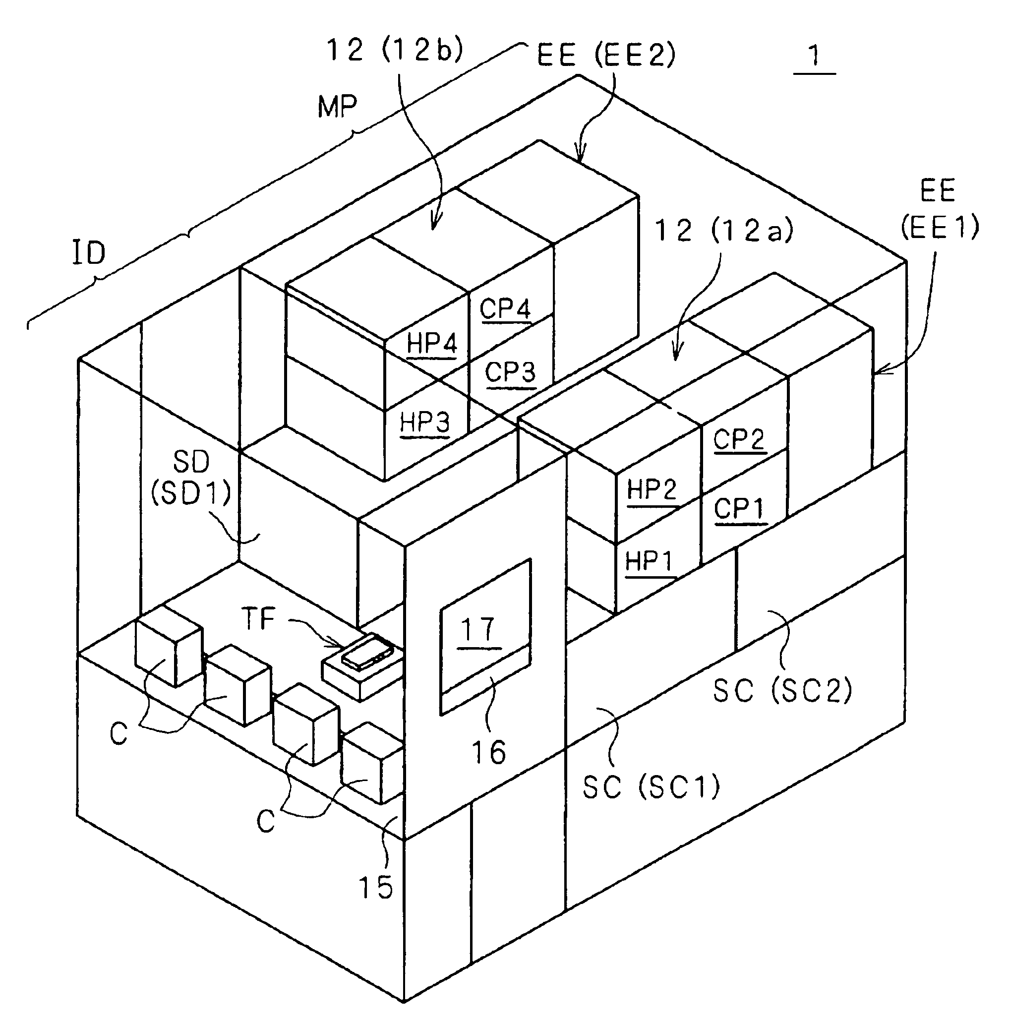
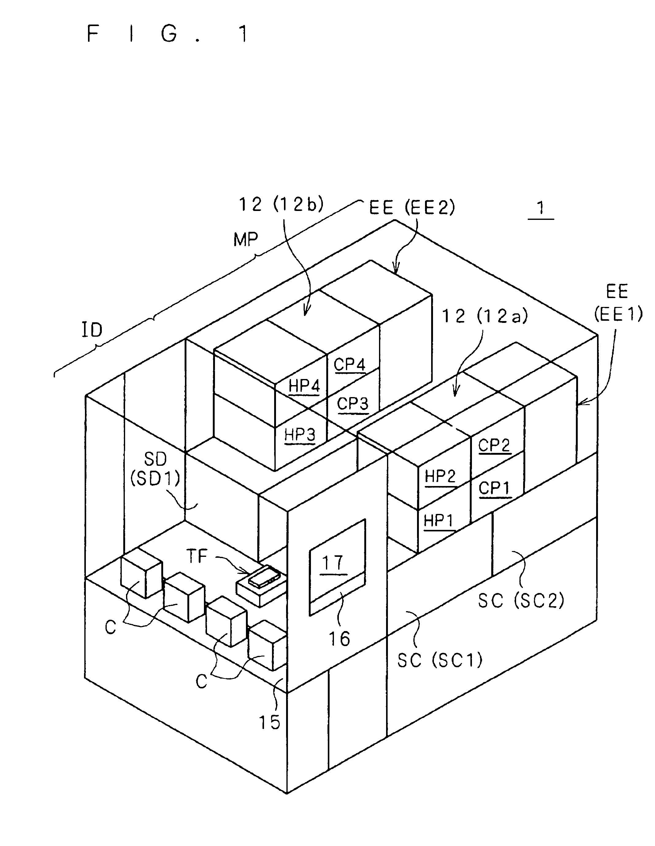
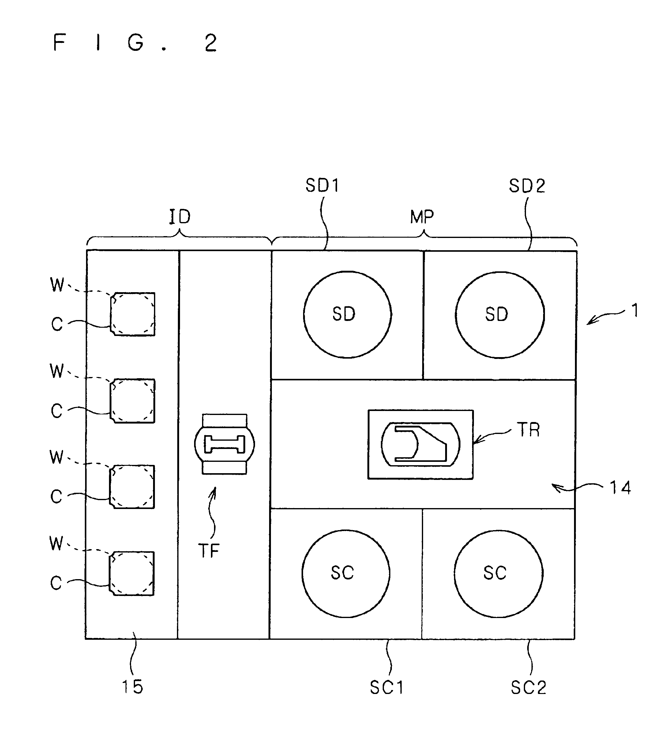
[0022]FIG. 1 is a perspective view showing the outline of the entire substrate processing apparatus 1 according to a first preferred embodiment of the present invention. FIG. 2 is a plan view showing the schematic configuration of the substrate processing apparatus 1. This apparatus 1 is a substrate processing apparatus that performs resist application process and development process to a substrate W (i.e., so-called coater and developer), which comprises mainly an indexer ID and a unit arrangement part MP.
[0023]The indexer ID is provided with a transfer robot TF and a mount stage 15. Four carriers C can be horizontally arranged and mounted on the mount stage 15. A multi-stage receiving grooves are provided in each carrier C, so that a single substrate W is stored in its horizontal position (with its main surface oriented along a horizontal plane) in each groove. Accordingly, each carrier C can store a plurality of substrates W (e.g., 25 substrates) in their horizontal position and ...
second preferred embodiment
[0061]The processing manner in the substrate processing apparatus is not limited to that described in the first preferred embodiment. The following is a manner with which it is possible to further suppress the power consumption in the normal mode of the first preferred embodiment. Since a substrate processing apparatus 1 of a second preferred embodiment has basically the same configuration as the first preferred embodiment, its description is omitted herein.
[0062]FIG. 6 is a diagram showing the flow of operation in the substrate processing apparatus 1 according to the second preferred embodiment. The flow of FIG. 6 is the same as that of FIG. 5, except for the point that when the normal mode is selected, steps S21 and step S22 are added. The operations other than that irrelevant to this point, such as the operations in the energy saving mode, are basically the same as that in the first preferred embodiment. Therefore, similar reference numerals are used, and their description is omi...
third preferred embodiment
[0066]The following is a manner with which it is possible to further suppress the power consumption in the energy saving mode in the second preferred embodiment. Also in a third preferred embodiment, the configuration of a substrate processing apparatus 1 is basically the same as that of the foregoing embodiment, and its description is omitted herein.
[0067]FIG. 7 is the flow of operations in the substrate processing apparatus 1 according to the third preferred embodiment. The flow of FIG. 7 is the same as that of FIG. 6, except that instead of step S8, steps S31 is provided when the energy saving mode is selected, and that a point to which the program returns in the case of “NO” in step S11 is different. The operations other than operations irrelevant to these differences, such as the operations in the normal mode, are basically the same as that in the second preferred embodiment. Therefore, similar reference numerals are used and their description is omitted herein.
[0068]The third ...
PUM
 Abstract
Description
Claims
Application Information
 - R&D
- Intellectual Property
- Life Sciences
- Materials
- Tech Scout
- Unparalleled Data Quality
- Higher Quality Content
- 60% Fewer Hallucinations
Browse by: Latest US Patents, China's latest patents, Technical Efficacy Thesaurus, Application Domain, Technology Topic, Popular Technical Reports.
© 2025 PatSnap. All rights reserved.Legal|Privacy policy|Modern Slavery Act Transparency Statement|Sitemap|About US| Contact US: help@patsnap.com


