
Clear ice making apparatus, clear ice making method and refrigerator

a clear ice making and clear ice technology, applied in the field of clear ice making apparatus and clear ice making method, can solve the problems of increased air molecules, increased time required to make ice, and excessive concentration of air molecules in the region containing an excessive concentration of air molecules

Inactive Publication Date: 2005-08-30
PANASONIC CORP
View PDF13 Cites 79 Cited by
  • Summary
  • Abstract
  • Description
  • Claims
  • Application Information

AI Technical Summary

Benefits of technology

"The present invention relates to a clear ice making apparatus and a method for making clear ice. The apparatus includes a freezing space, a tray placed in the freezing space, and water supply means of supplying water to the tray. The apparatus is designed to make ice at a high rate of speed with minimal air bubble formation. The invention also includes a method for controlling the water supply interval and amount based on the temperature of the tray to prevent excess water from being supplied. The clear ice making apparatus can be used in refrigerators and can be adapted to make ice at different temperatures. The technical effects of the invention include improved ice making efficiency, reduced air bubble formation, and improved ice quality."

Problems solved by technology

A large problem about making a clear ice is how to prevent air bubbles produced during freezing from being trapped in the resulting ice.
Another problem is how to prevent hard ions contained in highly hard well water or mineral water in themselves from being deposited or air bubbles from being produced by impurities such as hard ions becoming cores thereof.
Therefore, in order to make a clear ice, it is essential to make an ice as slowly as possible, and thus, there is a problem in that the time required to make an ice cannot be shortened even if it is desired.
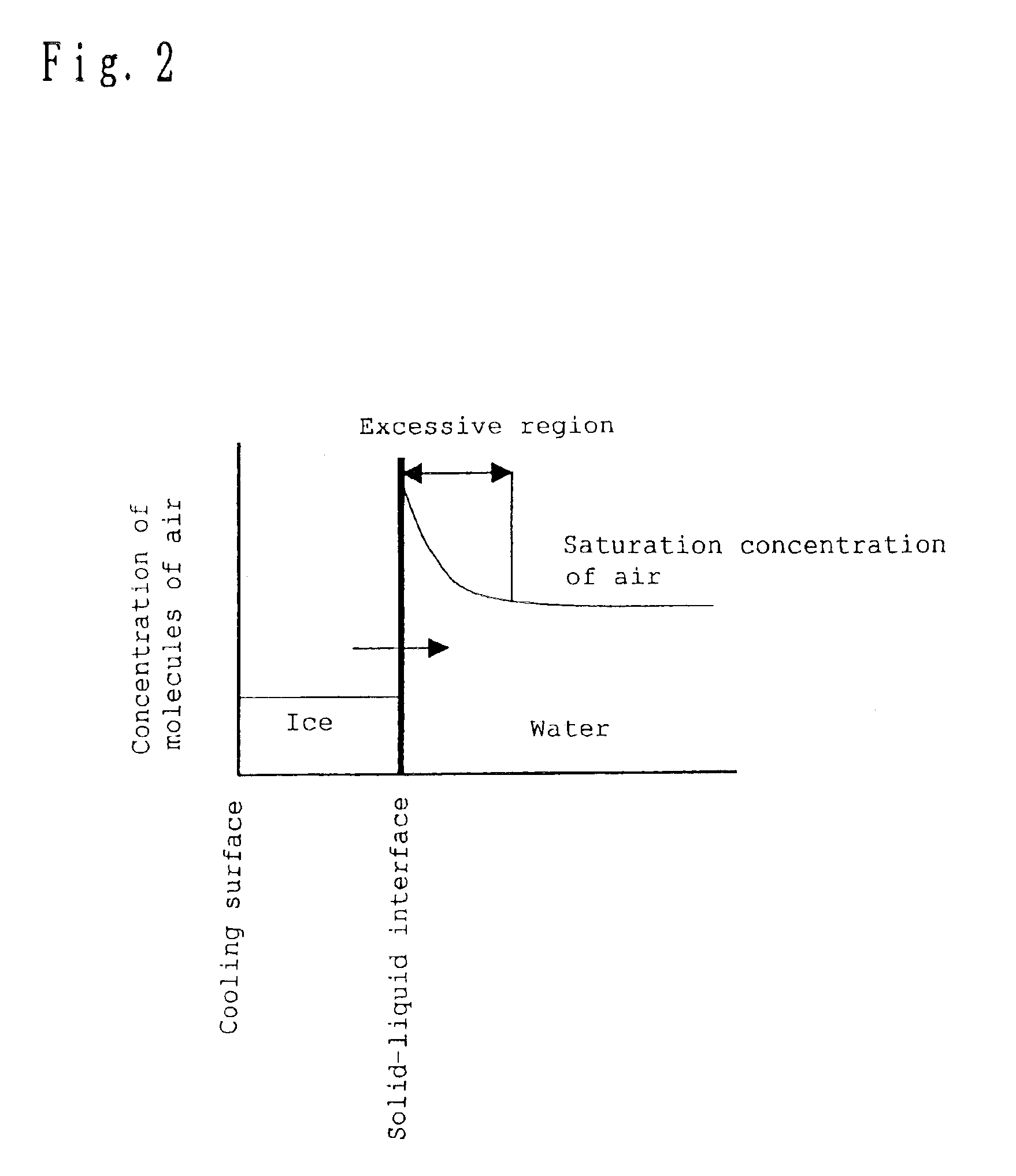
However, if the interface shift rate is low, molecules of air excluded from the ice are accumulated in water near the interface, thereby forming a region containing an excessive concentration of molecules of air.
Such excessive molecules of air increase as the ice grows, and then, when the amount thereof go beyond a certain limit, the molecules form a macroscopic air bubble, which is eventually trapped in the growing ice.
Thus, the hard ions may be accumulated in the surface of the resulting ice to make the ice cloudy.
However, there is a problem in that the rate of ice making is extremely low, and it takes several days to make an ice.
Furthermore, the process of setting an opening of the ice making tray face down and suppling in the shape of a fountain into it involves a bulky apparatus and thus, is hot suitable for household application.
However, in the case where the air bubbles produced are small, there is a problem in that the bubbles are not separated from the interface between the ice and water and are trapped in the ice.
However, it involves a large-scale arrangement, resulting in a significant increase of cost.
Furthermore, it has a problem in that if ice making takes a long time, air is dissolved again in the degassed water, air bubbles are produced during crystallization, and thus, an ice with a high transparency cannot be obtained.
However, the process has a problem in that, for the household and industrial refrigerators, it is required to make ices in a tray, and thus, an ice similar to the natural ice stalagmitic cannot be made.
As described above, conventional ice making apparatus have a problem in that it is difficult to make an ice with a high transparency.

Method used


Image

  • Clear ice making apparatus, clear ice making method and refrigerator
  • Clear ice making apparatus, clear ice making method and refrigerator
  • Clear ice making apparatus, clear ice making method and refrigerator

Examples


embodiment 1

(Embodiment 1)

[0166]In conventional ice making processes, a significant consideration is how to prevent hard ions or dissolved air in tap or well water from remaining in the resulting ice in order to make the ice clear. According to this embodiment, a clear ice is made by preventing dissolved air (about 40 ppm at a temperature of 0° C. and under a pressure of 1 atmosphere) from remaining in the resulting ice and preventing an air bubble core from being generated in the liquid layer to attain efficient degassing, and by trapping, rather than removing, impurities including hard ions in the resulting ice such as in a grain boundary.

[0167]First, a mechanism for efficiently suppressing generation of an air bubble by intermittently supplying water from water supply means (not shown) will be described.

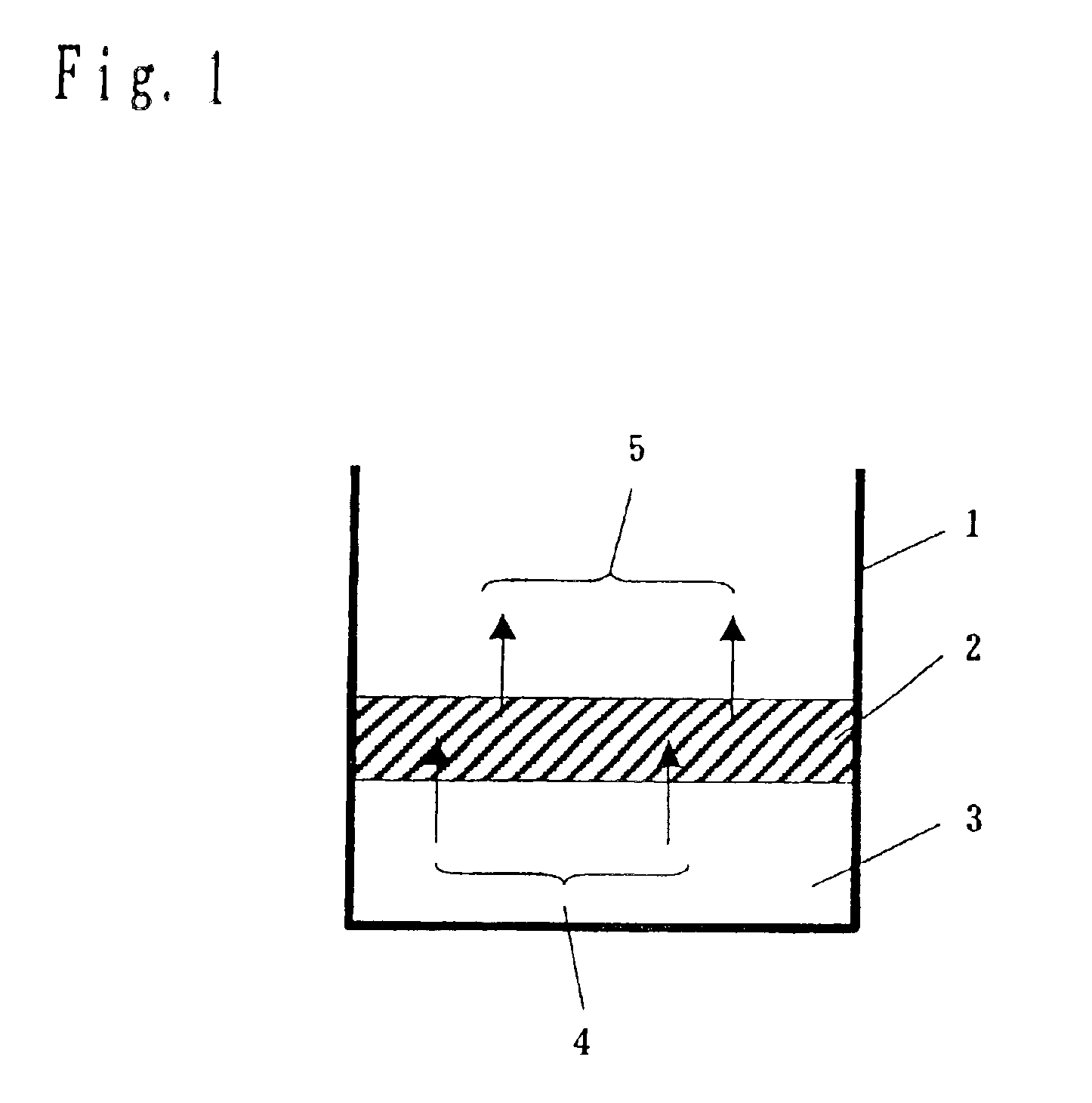
[0168]Referring to FIG. 1, part of water in an ice making tray 1 is frozen into an ice 3 and the rest remains as water 2. Although not shown in FIG. 1, in order to keep the bottom part of the...

embodiment 2

(Embodiment 2)

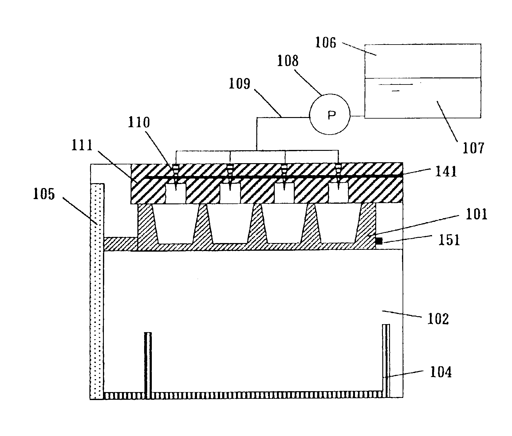
[0198]An ice making apparatus for making a clear ice is shown in FIG. 7. The ice making apparatus is incorporated in a refrigerator shown in FIG. 8. In FIG. 8, reference numeral 121 denotes a refrigerating room, reference numeral 122 denotes a vegetable room, reference numeral 123 denotes an ice making room, reference numeral 124 denotes a freezing room, reference numeral 125 denotes a control panel and reference numeral 126 denotes an ice making start button.

[0199]A freezing compartment 102, which serves as a freezing space of the ice making apparatus shown in FIG. 7 described above and is kept at a temperature at which water is crystallized, has a door 105. An opening 101a is provided at the top of an ice making tray 101.

[0200]The ice making tray 101 may be made of a resin, such as PP or PE, or a metal, such as aluminum. If the ice making tray is made of a resin, the thickness of the resin is varied between the bottom part and the upper part in such a manner that the...

embodiment 3

(Embodiment 3)

[0205]In the following, a third embodiment for making a clear ice will be described in detail with reference to FIG. 10.

[0206]The third embodiment differs from the embodiment 2 in that a heater 141 is provided in the heat insulating material 111. In the embodiment 2, depending on the capability of the heat insulating material 111 used, a high heat insulating capability prevents the temperature difference between the upper part and the bottom part of the ice making tray 101 from being provided. Thus, the heat insulating material has to have a somewhat low capability. However, in this embodiment 3, the heater 141 is provided in the heat insulating material 111, so that even if the heat insulating material 111 has a high heat insulating capability, a temperature difference can be provided between the upper part and the bottom part of the ice making tray 101. Furthermore, when ice making is completed, water in the water feed nozzle 110 and water feed pipe 109 needs to be r...


PUM


Abstract

A clear ice making apparatus includes: a freezing space; a tray placed in the freezing space and having a lower temperature at a bottom part thereof than at an upper part thereof; and a water supply unit of supplying water to the tray from the top thereof, in which ice is made at an ice making rate of 5 μm / s or lower, a part of a liquid-phase section of water in the tray which part is in contact with atmosphere is frozen to complete the ice making, the liquid-phase section of water is not entirely supercooled before the ice making is completed, and the concentration of air in the liquid-phase section of water in the tray is equal to or lower than an excessive concentration of air.

Description

BACKGROUND OF THE INVENTION[0001]1. Field of the Invention[0002]The present invention relates to a clear ice making apparatus and a clear ice making method for making a clear ice in a household refrigerator.[0003]2. Related Art of the Invention[0004]In conventional household refrigerators, to make a clear ice, an ice making tray is vibrated once water is poured into it, thereby preventing air bubbles produced during freezing from remaining in the resulting ice, or water having a dissolved gas such as air previously removed therefrom is used.[0005]Alternatively, once water has poured into an ice making tray, the upper part of the ice making tray is heated to develop a temperature difference between the upper and lower parts of the ice making tray, thereby preventing air bubbles produced during freezing from remaining in the resulting ice.[0006]Alternatively, in addition to avoiding air bubbles, to prevent hard ions such as calcium ions from being deposited in the resulting ice and th...

Claims


Application Information

Patent Timeline
Patent Type & Authority Patents(United States)
IPC IPC(8): F25C5/00F25C5/08F25C1/18F25C1/04
CPCF25C1/18F25C5/08F25C1/04F25C2305/022F25C2400/10F25C2400/14F25C2600/04F25C2305/0221
Inventor TAKAHASHI, YASUHITOTUSIMA, KATUTOSIKIDA, TAKUMIISHII, YUKOTATSUI, HIROSHIHAMADA, KAZUYUKI
Owner PANASONIC CORP
Learn More