Compound fabrication process and apparatus

a technology of compound fabrication and process, applied in the direction of manufacturing tools, electrical-based machining electrodes, other manufacturing equipment/tools, etc., can solve the problem that no machine in the prior art has the capability to perform all the above-listed steps

Inactive Publication Date: 2005-08-30
NAT UNIV OF SINGAPORE
View PDF22 Cites 14 Cited by
  • Summary
  • Abstract
  • Description
  • Claims
  • Application Information

AI Technical Summary

Benefits of technology

[0006]The objective of the invention is to provide an improved fabrication process and apparatus through which multiple manufacturing steps can be performed on a si...

Problems solved by technology

No machine in the prior art has the capability ...

Method used


Image

  • Compound fabrication process and apparatus
  • Compound fabrication process and apparatus
  • Compound fabrication process and apparatus

Examples


Embodiment Construction

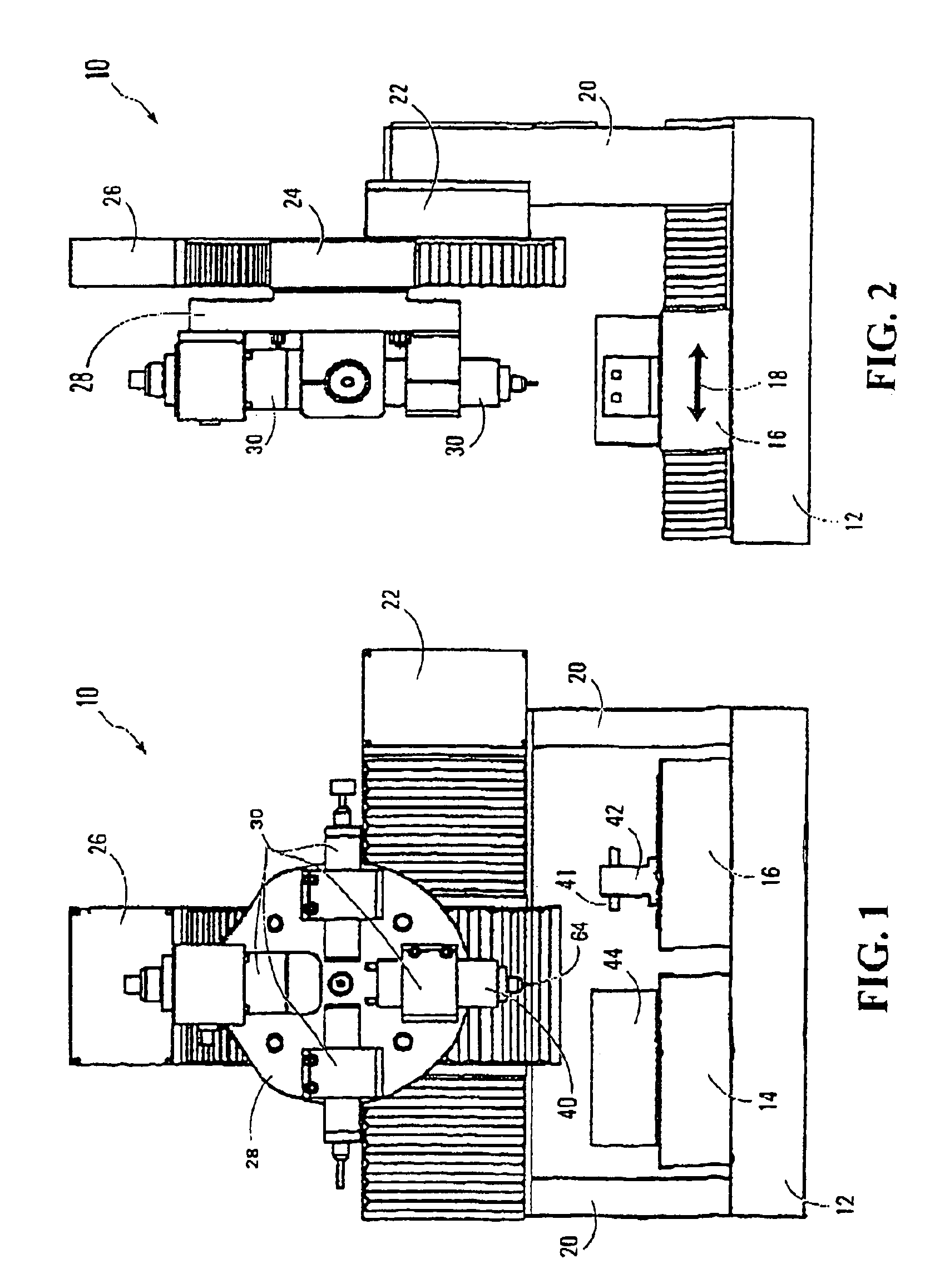
[0023]As shown in FIG. 1, a machine tool 10 in accordance with the invention comprises a base frame 12 upon which is supported a pair of beds 14, 16 each of which is independently moveable under a controlled drive system (not shown) to move in the fore-and-aft direction of the machine tool as indicated by the arrow 18 in FIG. 2. Each of the beds 14 and 16 as will be more fully explained hereafter forms one component of a machining station for carrying out operations on workpieces.

[0024]Rigidly attached to the base frame 12 are a pair of laterally spaced vertical pillars 20 the upper ends of which are rigidly connected to opposite ends of a horizontal crossbeam 22 which spans the width of the base frame as seen in FIG. 1.

[0025]In known manner, the crossbeam provides a horizontal guide for movement of a carriage 24 thereon, this carriage in turn providing guidance for vertical movement of a linear slide 26 therein. The linear slide in turn provides a mounting for various tooling or wo...


PUM


Abstract

A miniature machine tool for micro-machining is capable of performing on a workpiece at least one conventional mechanical machining operation and another micro-machining operation such as electrochemical machining (ECM), electro deposit machining (EDM), micro-milling or micro-turning or micro-drilling. The machine tool includes a holder in which the workpiece is clamped during all successive machining operations so that the machining operations may be performed in succession without intervening reclamping of the workpiece. This increases dimensional accuracy when micro-machining high-precision components.

Description

BACKGROUND OF THE INVENTION[0001]a) Field of the Invention[0002]This invention relates to a new or improved compound fabrication process and apparatus therefor, and in particular to the development of a miniature machine tool for manufacture of micro, high precision components.[0003]b) Description of the Prior Art[0004]In general, conventional machine tools are used to manufacture micro components. Usually the manufacture of such micro components requires multiple machining processes such as micro Electrode Discharge Machining (EDM), micro Electro Chemical Machining (ECM), micro milling, micro turning and micro drilling. Therefore to manufacture a simple part may entail use of more than one machine, depending on the geometry of the workpiece. For example to machine a micron sized hole in a workpiece one may have to first machine an electrode using turning, milling or other processes. The machined electrode will have to be placed in the spindle of an EDM machine to machine the micron...

Claims


Application Information

Patent Timeline
IPC IPC(8): B23Q39/00B23Q39/02B23P23/00B23P23/02
CPCB23H1/00B23H1/04B23H5/02B23H5/04B23H9/00B23Q39/02B23P23/02Y10T29/5114B23Q2039/004Y10T29/5136Y10T29/5152
Inventor RAHMAN, MUSTAFIZURSAN, WONG YOKEKUMAR, A. SENTHILNEOW, POO AUNSEOK, LIM HANMIYAZAWA, SHINICHI
Owner NAT UNIV OF SINGAPORE
Why Eureka
Try Eureka