Electronic timepiece including rotary weight and antenna

Active Publication Date: 2005-08-23
SEIKO EPSON CORP
View PDF9 Cites 26 Cited by
  • Summary
  • Abstract
  • Description
  • Claims
  • Application Information

AI Technical Summary

Benefits of technology

[0017]Therefore, since the electronic timepiece of the present invention receives wireless information, and also performs the power generation by the rotary weight and the generator, it can perform the power generation regardless of weather or season, and since rapid power generation can be also performed, a very convenient electronic timepiece can be provided. Further, it is preferable to install an accelerating wheel train between the rotary weight and the rotor.
[0071]By such a structure, since the antenna and the band for the wristwatch do not overlap, wireless radio waves interlinked to the antenna can be guaranteed, and the receiving sensitivity of the antenna can be highly maintained. If the band for the wristwatch is made from a conductive material, the wireless radio waves can be drawn into the band for the wristwatch, but if the antenna and the band for the wristwatch do not overlap, even if the wireless radio waves can be drawn into the band for the wristwatch, the impact on the interlink magnetic flux of the antenna can be reduced.

Problems solved by technology

Such a radio wave clock is normally driven by battery, but since power is consumed by radio wave reception, the lifetime of the battery is shorter than a normal clock, there is a problem that the battery should be replaced very often.
However, there is a problem in a solar power-generation mechanism that it does not always efficiently operate according to daylight amount (for example, cloudy or rainy weather), seasons (for example, winter), regions (for example, high latitude region), etc., so that it sometimes cannot supply power.
Because of this, if sufficient power is not supplied to the receiving mechanism, time information cannot be received, or wrong time information is received, the receiving sensitivity of the receiving mechanism is decreased.
Further, there is also a problem that a rapid charge is impossible in the solar battery if light is weak.
Because of this, the radio wave clock having the solar power-generation mechanism is not necessarily a convenient clock.
Therefore, there occurs a new problem that the standard radio waves cannot be received if the power-generation mechanism using the rotary weight is installed in the radio wave clock.
Such a problem is not limited to an electronic timepiece having a radio wave correction function, and it is a common problem in various electronic apparatus having a power-generation mechanism by a rotary weight, and an antenna receiving wireless information from the outside.

Method used


Image

  • Electronic timepiece including rotary weight and antenna
  • Electronic timepiece including rotary weight and antenna
  • Electronic timepiece including rotary weight and antenna

Examples


first embodiment

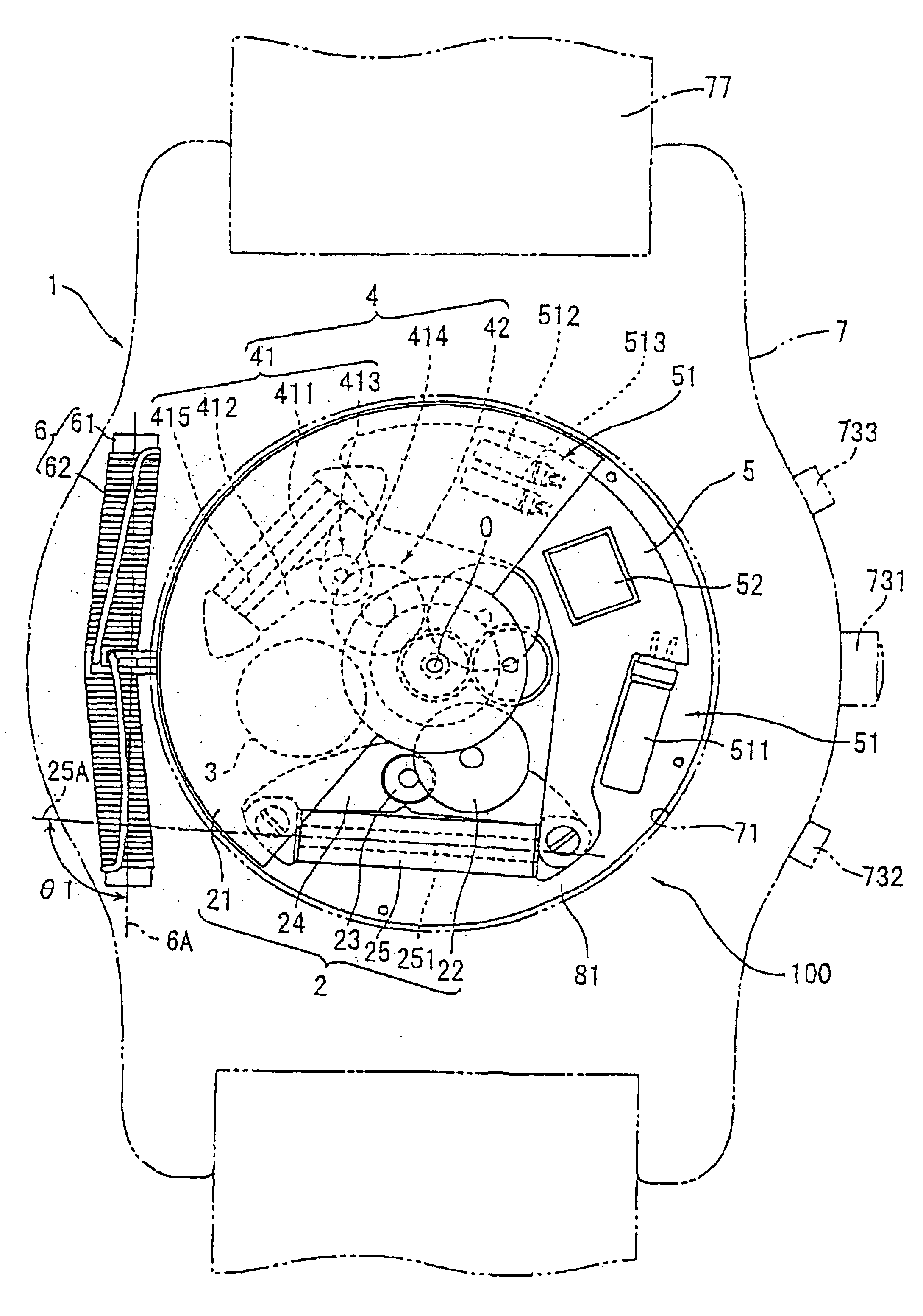
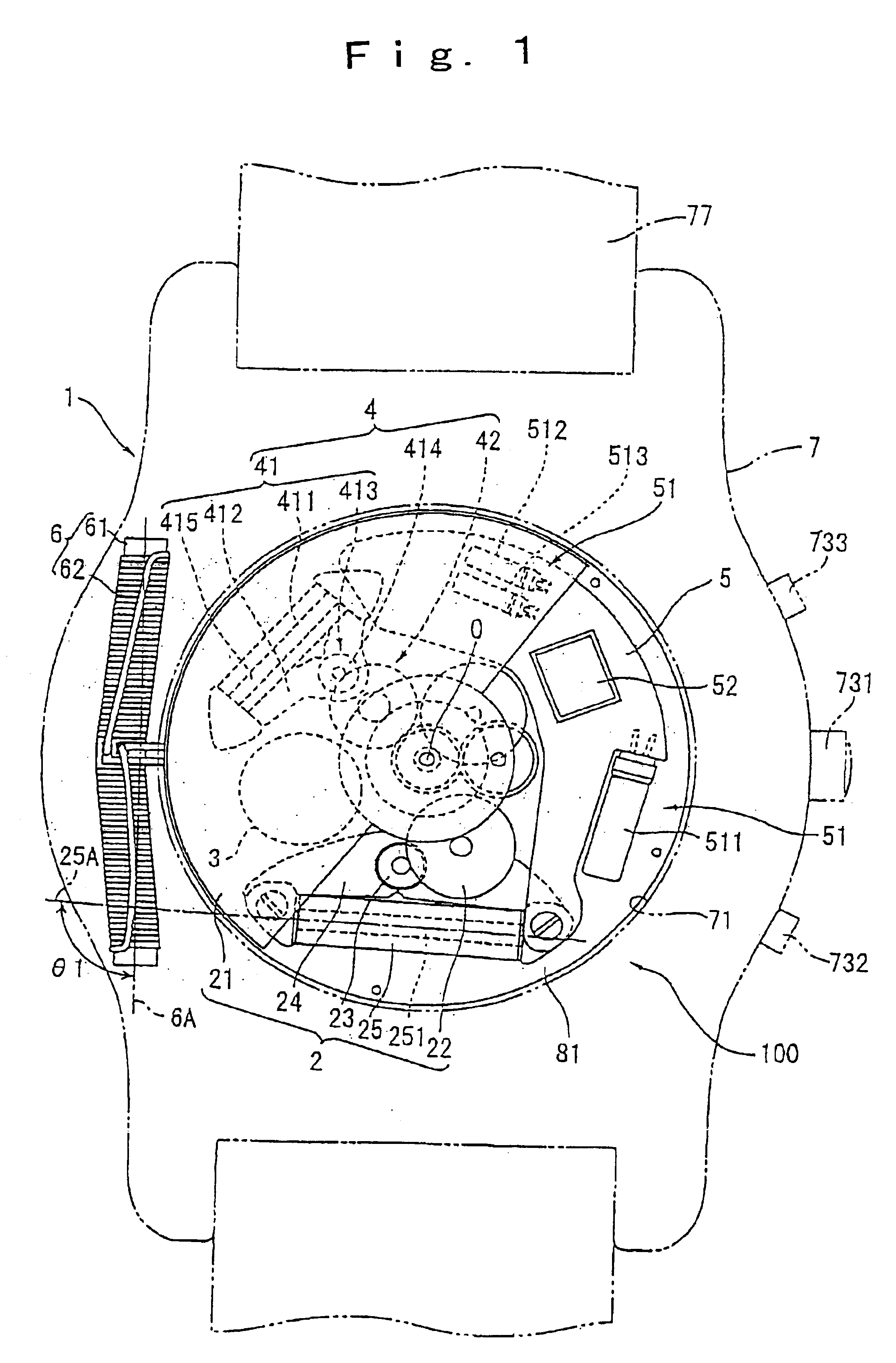
[0095]FIG. 1 illustrates a wristwatch typed radio wave clock according to an electronic timepiece of a first embodiment of the present invention. FIG. 1 is a plane view of the radio wave clock with a back lid of the radio wave clock removed. FIG. 2 is a cross-sectional view of the main parts of FIG. 1. Incidentally, in FIG. 1, it is assumed that the lower part of the drawing sheet is at the 6 o'clock direction, the upper part is at the 12 o'clock direction and right part is at the 3 o'clock direction. the drawing sheet is a 6 o'clock direction, downside is a 12 o'clock direction, and right is a 3 o'clock direction.

[0096]A radio wave clock 1 includes a body case 7, a movement 100 for clock placed inside the body case 7, and an antenna 6 for receiving standard radio wave including time information as wireless information.

[0097]The body case 7 is substantially ring-shaped, and made from nonconductive material such as ceramic and synthetic resin, or diamagnetic material such as brass, g...

second embodiment

[0142]FIG. 3 illustrates a radio wave clock 1 according to the electronic timepiece of a second embodiment of the present invention. The radio wave clock 1 has basically the same structure as that of the first embodiment, but the structure of the second embodiment is different from that of the first embodiment in the placement of the antenna 6, the secondary battery 3, the power-generation coil 25, and the motor coil 411.

[0143]In this embodiment, the antenna 6 and the power-generation coil 25 are placed diametrically opposite with respect to the center O of rotation of a rotary weight 21. And, in the structure of the radio wave clock 1, the antenna 6 and the power-generation coil 25 are preferably placed furthest away from each other.

[0144]The secondary battery 3 and a motor 41 for driving hands are placed between the antenna 6 and the power-generation coil 25. Coil core 415 of the motor coil 411 and the case of the secondary battery 3 form magnetic field shielding means. The magnet...

third embodiment

[0149]FIG. 4 illustrates a radio wave clock 1 according to the electronic timepiece of a third embodiment of the present invention. The radio wave clock 1 has basically the same structure as that of the second embodiment, but the structure of the third embodiment is different from that of the second embodiment as follows.

[0150]That is, the second embodiment has a structure in which only one secondary battery 3 is installed, but two secondary batteries 3a, 3b are installed in the third embodiment. And, between a power-generation coil 25 and an antenna 6, there are installed the two secondary batteries 3a, 3b and a motor 41 for driving hands.

[0151]Therefore, the magnetic field shielding means mainly includes coil core 415 of motor coil 411, and each case of the secondary batteries 3a, 3b, and also includes the sear train such as a wheel train part 42 or a power transmission part 22 placed between the antenna 6 and the power-generation coil 25, and metallic parts such as a rotary weigh...


PUM


Abstract

The driving portion 4 is composed of multipolar motor 43. The multipolar motor 43 includes a coil 431 for multipolar motor 43, a stator 432 for multipolar motor 43, for transmitting a magnetic field from coil 431, and a rotor 433 for multipolar motor 43 installed ratably in a stator hole of stator 432. A multipolar magnet is provided on a peripheral part of rotor 433. A plurality of teeth are formed on stator 432 toward rotor 433. Clock hands for displaying time are installed on the rotation axis of rotor 433.

Description

TECHNICAL FIELD[0001]The present invention relates to an electronic timepiece and an electronic apparatus, and more specifically, it relates to an electronic timepiece and an electronic apparatus having a power-generation mechanism by a rotary weight and a receiving mechanism for receiving wireless information.BACKGROUND ART[0002]As an electronic apparatus such as an electronic timepiece having a function for receiving wireless information, there is known, for example, a radio wave clock for receiving time information wirelessly transmitted (standard radio waves) and performing time correction. Such a radio wave clock is normally driven by battery, but since power is consumed by radio wave reception, the lifetime of the battery is shorter than a normal clock, there is a problem that the battery should be replaced very often.[0003]Because of this, a radio wave clock having a solar power-generation mechanism installed as a power-generation mechanism is known (for example, Japanese Une...

Claims


Application Information

Patent Timeline
IPC IPC(8): G04C10/00G04G1/00G04G1/06G04C3/02G04B17/00G04G21/04G04R20/00G04R20/08G04R60/02G04R60/10
CPCG04C10/00G04G5/002G04G21/04G04R60/10G04C3/02G04R60/02
Inventor FUJIMORI, SHIGEYUKI
Owner SEIKO EPSON CORP
Why Eureka
Try Eureka