
Tubular reactor for catalytic gas phase reactions

Inactive Publication Date: 2005-08-23
MAN ENERGY SOLUTIONS SE
View PDF7 Cites 28 Cited by
  • Summary
  • Abstract
  • Description
  • Claims
  • Application Information

AI Technical Summary

Benefits of technology

[0010]The respective heat insulation zone at the tube plate on the gas inlet side in the shape of a chamber or formed by stream-calming structures has the effect that the gas plate on the inlet side of the reaction gas and the surrounding area of the gas inlet hood is kept comparatively cool, without the need for any limitations in the process, the reactor design or the heat exchanger material to be used. Through a respective design of the heat insulation zone, the temperature gradient may be kept low regardless of the comparatively cold tube plate that connects to the reactor jacket as is desirable for keeping the temperature stress low.

Problems solved by technology

In this course, secondary reactions that are harmful to the process or even ignition and deflagration may occur, especially in the immediate area surrounding the generally relatively hot tube plate.
However, in the end, none of these measures proved effective or at least dependable for preventing the above mentioned secondary reactions.
It is understood that such a process is limited to certain applications.
In addition, the isolation tubes which extend in a pivotal manner into the contact tubes for the purpose of compensating for differing heat expansions form undesirable contractions for adding and removing the catalyst.
However, such materials, such as artificial resin that must be sufficiently fluid during pouring to distribute itself around the tubes in a desired manner exhibit only a limited temperature resistance that makes them unsuitable for the application of molten salts, for example, as a heat carrier.
If they had to carry the liquid heat carrier in addition to the weight of the tubes, then the usual immediate anchoring at the reactor jacket would be unavoidable.

Method used


Image

  • Tubular reactor for catalytic gas phase reactions
  • Tubular reactor for catalytic gas phase reactions
  • Tubular reactor for catalytic gas phase reactions

Examples


Embodiment Construction

[0021]The present invention will now be described with reference to FIGS. 1–8 of the drawings. Identical elements in the various figures are identified by the same reference numerals.

[0022]Easily comparable elements that occur in the individual Figures were given the same reference number.

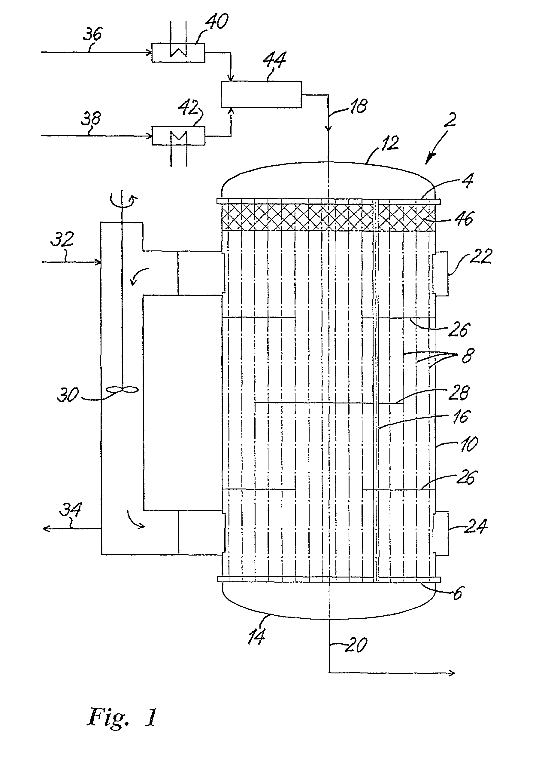
[0023]The tubular reactor 2 shown in FIG. 1 includes in typical manner a vertical tube bundle 8 that stretches inside a cylindrical reactor jacket 10 from a tube plate 4 at the gas inlet side to a tube plate 6 at the gas outlet side with the two tube plates 4 and 6 being attached to said cylindrical jacket in a sealed manner. The tube plate 4 at the gas inlet side is spanned by a gas inlet hood 12 and the tube plate 6 at the gas outlet side is spanned by a gas outlet hood 14, with both hoods being attached to the respective tube plate in a sealed manner. The individual tubes, e.g., 16, of the tube bundle 8 contain a gas-permeable catalytic mass. The reaction or process gas that is to be brought to ...


PUM


Abstract

A tubular reactor (2) for catalytic reactions with a heat carrier that inside a reactor jacket (10) circulates around a contact tube bundle (8), which extends between a tube plate (4; 6; 80; 82) at the reaction gas inlet side and one at the reaction gas outlet side with gas inlet and gas outlet hoods (12, 14) spanning the face sides of the two tube plates and containing reaction-inhibiting media in the zone of the tube plate on the gas inlet side, characterize themselves in that the reaction-inhibiting media consist entirely or in part of a heat insulation layer (46; 50; 64; 80) with openings for the tube cross-sections on at least one of the two sides of the respective tube plate (4; 60; 82). In this manner, either the respective tube plate (4; 60; 82) is insulated against the hot heat carrier or the reaction gas entering into the reactor is prevented from having contact with the comparatively hot tube plate in order to prevent harmful secondary reactions at the reactor inlet.

Description

BACKGROUND OF THE INVENTION[0001]The invention relates to a tubular reactor for catalytic gas phase reactions.[0002]Usually, such reactors exhibit a reactor jacket containing a heat carrier that circulates around a contact tube bundle, which extends between a tube plate at the gas inlet side and a tube plate at the gas outlet side, as well as gas inlet and gas outlet hoods spanning the face sides of the two tube plates. The process gas, usually a gas mixture, that is to be brought to reaction enters a contact tube that contains a catalytic mass via the gas inlet hood and after passing said contact tube exits the reactor via the gas outlet hood. The gas inlet may be located either on the top or bottom side, and as a whole the heat carrier may pass through the reactor in parallel flow or counter flow with regard to the process gas flow. The reactor can also have a multi-step design as shown, for example, in the German Patent No. DE 22 01 528 C, FIG. 5.[0003]Usually, the process gas st...

Claims


Application Information

Patent Timeline
IPC IPC(8): B01J8/02B01J8/06
CPCB01J8/067B01J2208/00212B01J2208/00221B01J2208/00256B01J2208/00495B01J2208/00522B01J2208/025B01J2219/00099B01J2219/00155B01J2219/00777F28F2270/00
Inventor GUETLHUBER, FRIEDRICH
Owner MAN ENERGY SOLUTIONS SE
Learn More