
Junction socket with a moveable contact piece

a technology of moving contact pieces and junction sockets, which is applied in the direction of coupling contact members, coupling device details, coupling device connections, etc., can solve the problems of reducing contact stability, increasing the cost of electronic components, and unable to solve the problem perfectly, so as to improve the contact stability of male terminals and prevent deformation

Inactive Publication Date: 2005-08-23
YAZAKI CORP
View PDF6 Cites 15 Cited by
  • Summary
  • Abstract
  • Description
  • Claims
  • Application Information

AI Technical Summary

Benefits of technology

The design enhances contact stability by preventing deformation of the resilient contact piece and maintaining consistent contact pressure, even with oblique insertions, thereby improving the reliability of electrical connections.

Problems solved by technology

However, there are problems as follows to be solved in this conventional junction socket.
This also may reduce contact stability.
However, this cannot solve the problem perfectly.
Further, managing precisely sizes of those including a plurality of small electronic components in the electrical junction box makes another problems such as increasing electronic components cost, or reducing assembling workability.

Method used


Image

  • Junction socket with a moveable contact piece
  • Junction socket with a moveable contact piece
  • Junction socket with a moveable contact piece

Examples


first embodiment

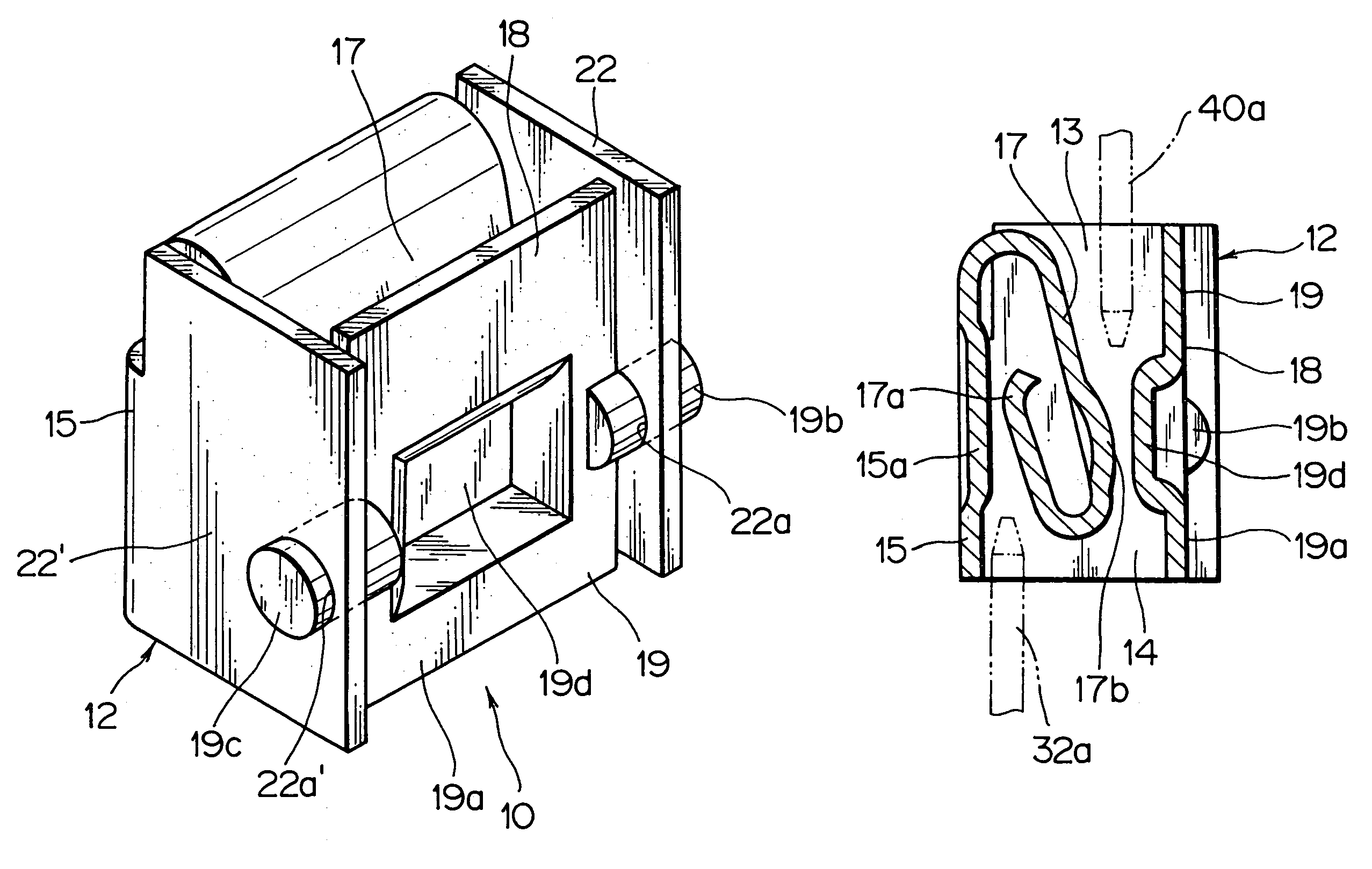
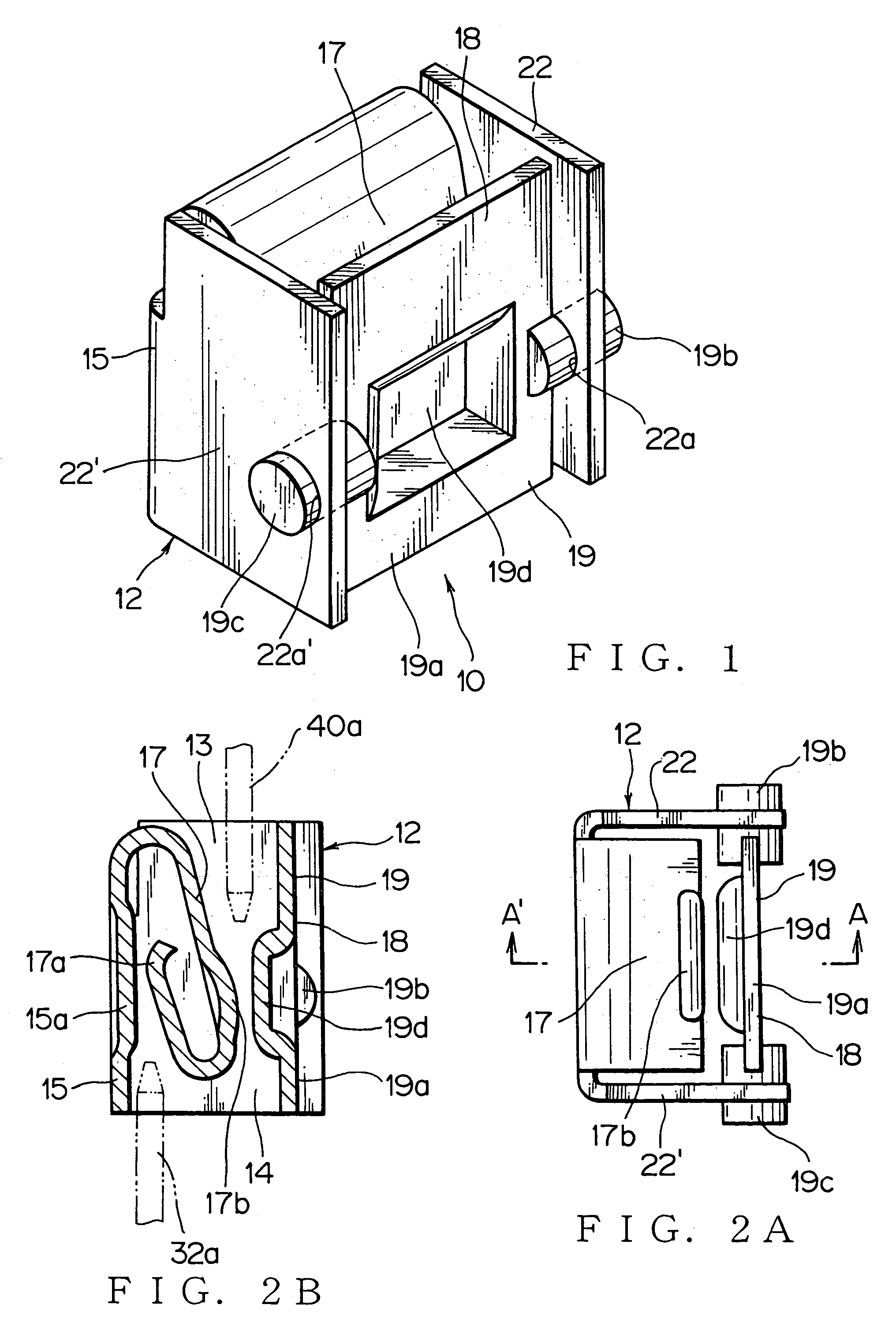
[0059]The junction socket 10 of this first embodiment prevents a resilient contact piece 17 from being pried to be damaged by the male terminals 32a, 40a being inserted into the junction socket 10. Further, this junction socket 10 guarantees stable contact pressure between the terminals, and thereby improves contact stability between the terminals.

[0060]This junction socket 10 has a receptacle 12 to receive upper and lower male terminals 40a, 32a in directions opposite to each other and to electrically connect them to each other. This junction socket includes a front wall 15; a rear wall 18; sidewalls 22, 22′ at both sides of the front and rear walls 15, 18; top and bottom openings 13, 14 formed respectively at both ends of the front and rear walls 15, 18; and the resilient contact piece 17 extended from the front wall 15, and bent twice inwardly in vicinities of the top and bottom openings 13, 14 of the receptacle 12. The rear wall 18 is configured with a movable contact piece 19 f...

second embodiment

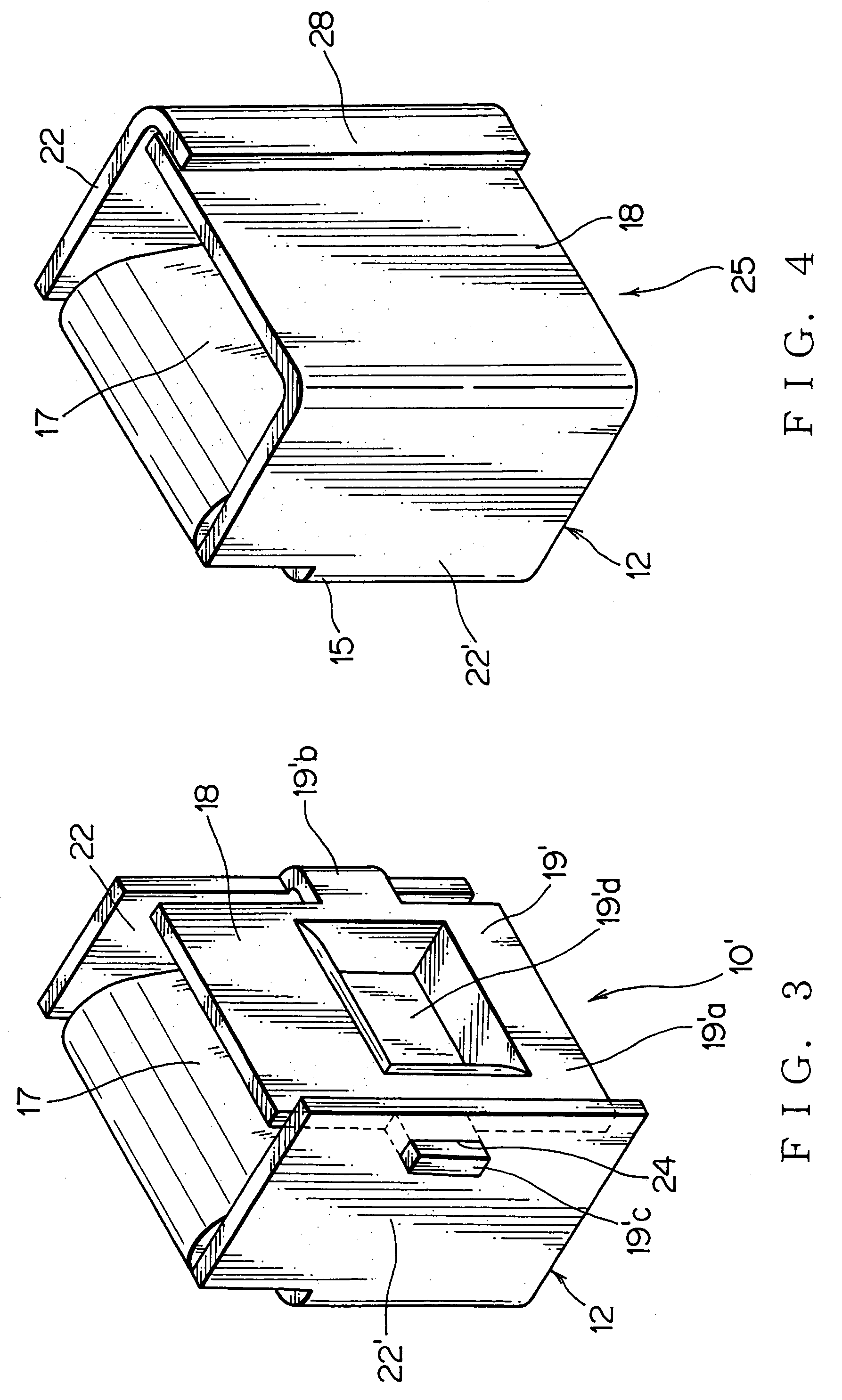
[0068]The junction socket 25 can compensate for angle errors of the two male terminals 32a, 40a, being inserted thereinto in directions opposite to each other, with a simple configuration. A resilient contact piece 17 is extended from a front wall 15, and bent twice inwardly in vicinities of an top and bottom openings 13, 14 of the receptacle 12. A first contact projection 26 facing to the resilient contact piece 17 is provided on the front wall 15. A second contact projection 27 facing to the resilient contact piece 17 is provided on the rear wall 18. When being inserted downward into the top opening 13 from a base of the resilient contact piece 17, the upper male terminal 40a is held between the resilient contact piece 17 and the second contact projection 27 on the rear wall 18. When being inserted upward into the bottom opening 14, the lower male terminal 32a is held between the resilient contact piece 17 and the first contact projection 26 on the front wall 15. Further, in this ...


PUM


Abstract

A receptacle of this junction socket includes a resilient contact piece extended from a front wall, and bent twice inwardly in vicinities of top and bottom openings of the receptacle; a movable contact piece as a rear wall facing to the resilient contact piece, and able to rotate around spindles provided on both of the sidewalls respectively. The receptacle receives upper and lower male terminals in directions opposite to each other, and electrically connects them to each other. When inserting the terminals, the movable contact piece rotates to align along an insertion direction of the upper male terminal.

Description

[0001]The priority application Number Japanese Patent Application No. 2003-364517 upon which this patent application is based is hereby incorporated by reference.BACKGROUND OF THE INVENTION[0002]1. Field of the Invention[0003]This invention relates to a junction socket applied to an electrical junction box for connecting wire harnesses to each other and the like. This junction socket is used for connecting a male terminal projecting from an end of a bus bar to a male terminal extended from an electronic component.[0004]2. Description of the Related Art[0005]Generally, a case of an electrical junction box, such as a fuse box, a relay box, a junction box, accommodates bus-bar-circuit boards, and they are stacked if necessary. Each of these bus-bar-circuit boards is configured with a plurality of bus bars and an insulating circuit board for supporting these bus bars. A fuse mounting block, a relay mounting block, and a connector mounting block for connecting a wire harness, are provide...

Claims


Application Information

Patent Timeline
Patent Type & Authority Patents(United States)
IPC IPC(8): H01R31/08H01R31/00H01R13/11H01R13/115H01R31/06
CPCH01R31/08Y10S439/949H01R11/09H01R13/113
Inventor YAGI, SAKAIMIYAZAKI, YASUTAKA
Owner YAZAKI CORP
Learn More