
Magnetic recording apparatus and system for driving a magnetic recording medium

a recording apparatus and magnetic recording technology, applied in the field of magnetic recording apparatus and magnetic recording method, can solve the problems of increasing the danger of excessive magnetization of the head pole by a large current amplitude, reducing the signal amplitude upon readout, and gentler magnetic field slope, so as to avoid excessive magnetization of the head pole. the effect of power supply to the recording head during the time corresponding to one recording pattern and reducing the power supply to the recording head

Inactive Publication Date: 2005-08-16
HITACHI GLOBAL STORAGE TECH JAPAN LTD
View PDF8 Cites 9 Cited by
  • Summary
  • Abstract
  • Description
  • Claims
  • Application Information

AI Technical Summary

Benefits of technology

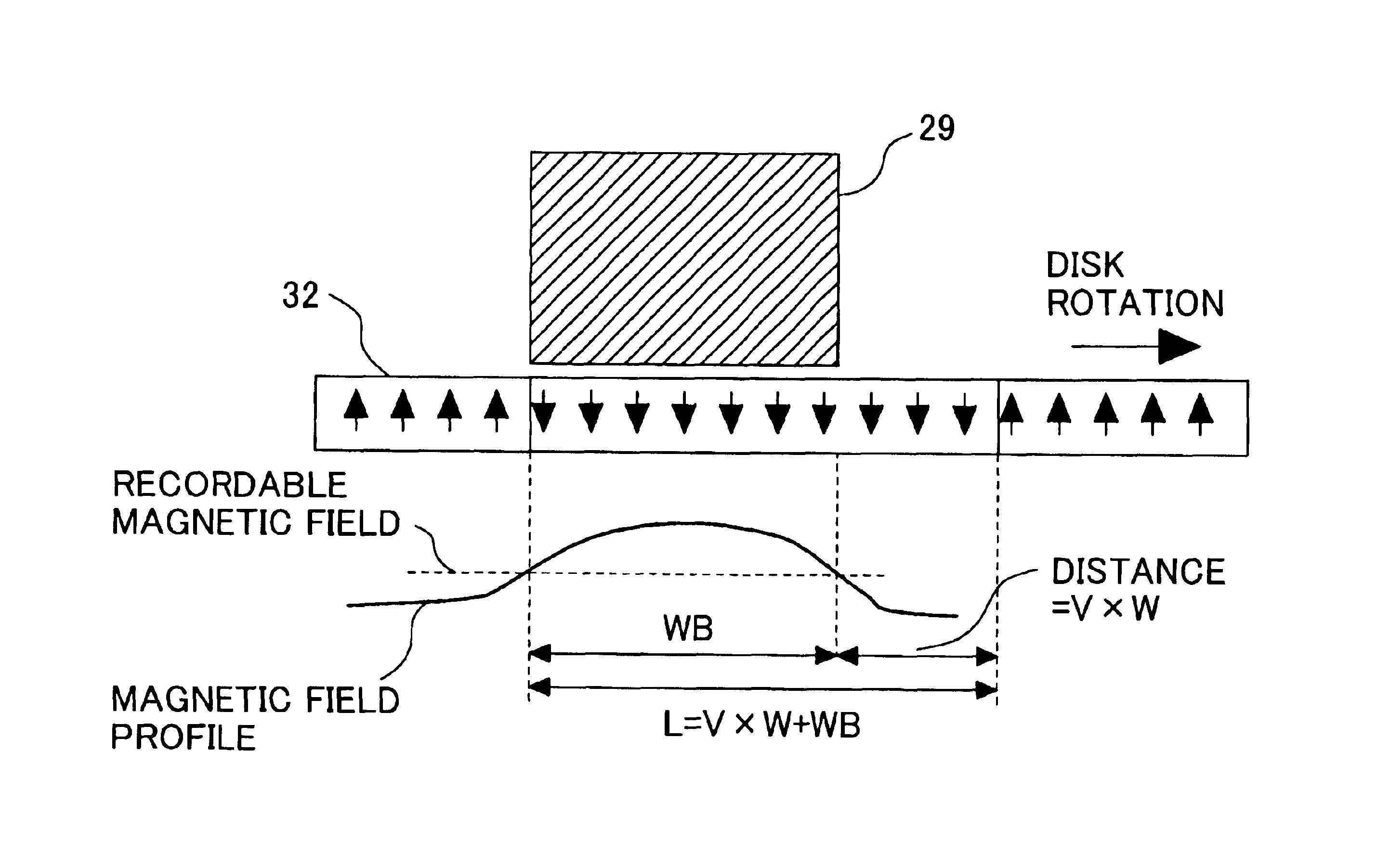
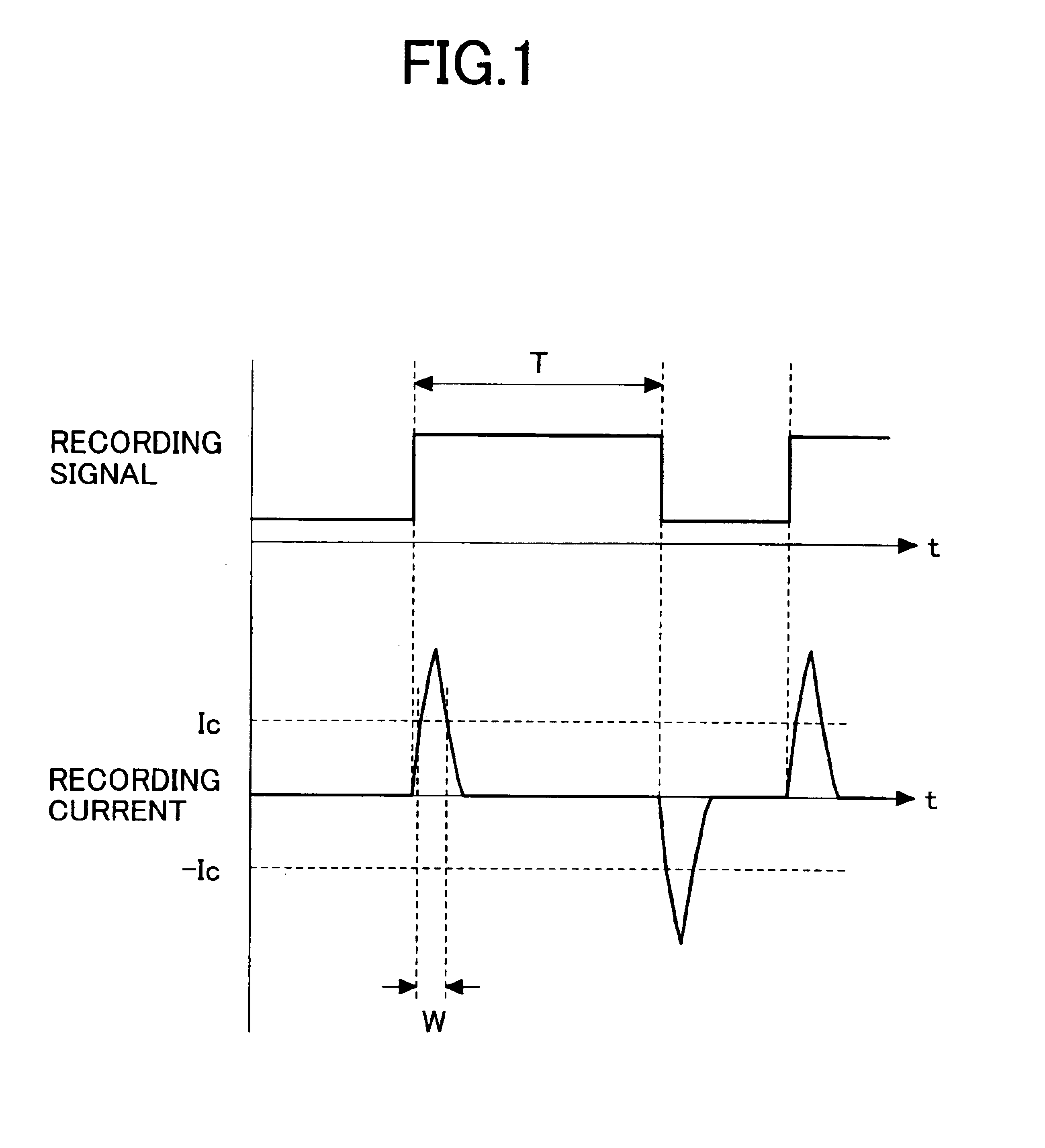
[0020]In this case, if the recording pattern time length T is reduced such that W>T, the portion of the waveform in which the current amplitude is reduced will be eliminated. Thus, the effect of the invention in such a case would be expected up to this pattern time length.
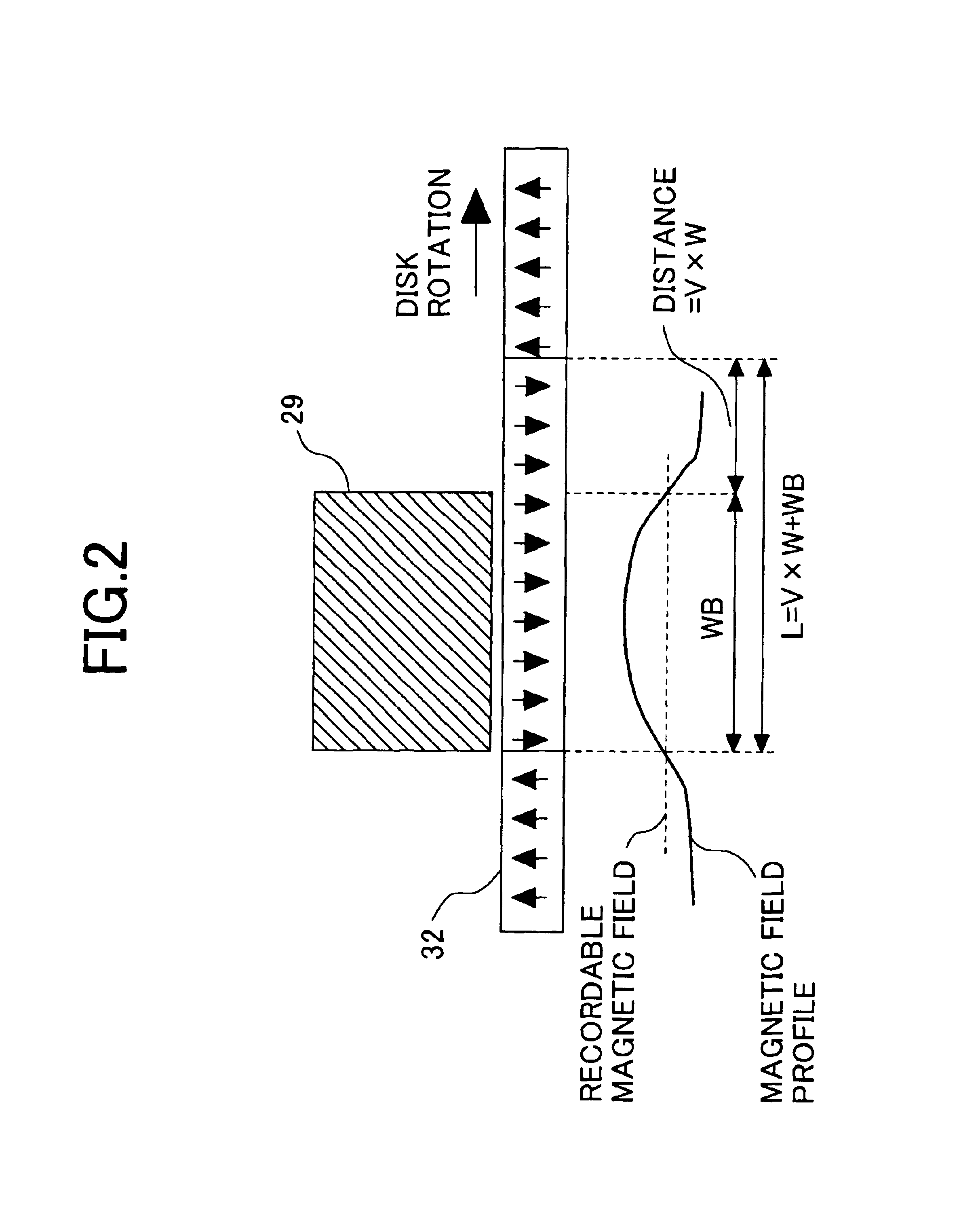
[0021]In the conventional recording current waveform, the recording current flows continuously during the entire time length the recording pattern. In the present invention, however, the time in which the current with a recordable current wavelength flows is limited to the time W. In the remaining time, either no recording current flows or a recording current with a less-than-recordable current amplitude flows. As a result, the power supplied to the recording head during the time corresponding to one recording pattern can be reduced. Thus, the power supplied to the recording head can be reduced even when the intensity of the current amplitude contributing to fast magnetic field inversion is the same as that of the conventional current waveform. This makes it possible to avoid the excessive magnetization of the head poles and contributes to high-density recording. Further, the reduction in the power supply to the head leads to a reduction in the amount of heat generated in the head, thereby preventing the deterioration of recording performance due to mechanical deformation of the head. Furthermore, the current supply circuit of the recording driver is made up of a pulse waveform generating block and can therefore be simplified, so that the current supply circuit can be adapted for high frequencies effectively.
[0022]The write bubble size depends on the structure of the recording head, the magnetic characteristics of the magnetic recording medium, and the distance between the recording head and the recording medium. By providing the recording current driver with a function for setting the time length of the recording current, modifications in the recording head, recording medium, or the maximum pattern size can be accommodated.
[0023]Thus, in accordance with the invention, high-density and high-frequency recording can be achieved without requiring changes in the magnetic characteristics of the magnetic recording medium or the structure of the recording head, or without particularly reducing the distance between the magnetic head and the magnetic recording medium.

Problems solved by technology

On the other hand, it also leads to an increased danger of the head pole being excessively magnetized by a large current amplitude.
Specifically, while the increase in overshoot amplitude helps to increase the magnetic field inversion speed, it can also cause an excessive magnetization after magnetic field inversion, which makes the magnetic field slope gentler.
As a result, the signal amplitude upon readout decreases, which is not suitable for high-density recording.
Thus, in the conventional current waveform, there is a tradeoff between an increase or decrease in the overshoot amplitude and the formation of a sharp boundary between recording patterns.
Further, an increase in the current amplitude also increases the power supplied to the head, so that the head may produce heat whereby the recording head could be subject to an increased risk of thermal-mechanical deformation.
As a result, the distance between the recording head and the recording medium could vary and a normal recording operation could be hindered.
Therefore, the method cannot be applied to the perpendicular recording system employing a single pole head having no gap.

Method used


Image

  • Magnetic recording apparatus and system for driving a magnetic recording medium
  • Magnetic recording apparatus and system for driving a magnetic recording medium
  • Magnetic recording apparatus and system for driving a magnetic recording medium

Examples


Embodiment Construction

[0036]The invention will be hereafter described by way of an embodiment with reference made to the drawings.

[0037]FIG. 3 shows a block diagram of an example of the magnetic recording apparatus according to the invention. The magnetic recording apparatus is of a known structure including a magnetic recording medium 13 rotated by a motor 12 for recording magnetic information, a magnetic head 14 mounting a recording head for recording information on the magnetic recording medium and a read head for reproduction. The apparatus also includes a recording driver 15 for supplying a recording current to the recording head, a preamplifier 16 and a readout circuit 17 for detecting and processing a signal from the read head, a controller 18, and a CPU 19. The recording head mounted on the magnetic head 14 is a single pole head having a main pole and an return pole. The magnetic recording medium 13 is a perpendicular magnetic recording medium made of a non-magnetic substrate on which a soft magn...


PUM

PropertyMeasurementUnit
currentaaaaaaaaaa
current amplitudeaaaaaaaaaa

Abstract

A magnetic recording apparatus suitable for high-density and high-frequency magnetic recording includes a recording head to the coil of which a recording current is supplied, the recording current having a waveform such that the conducting time length is shorter than the time length of a recording pattern.

Description

BACKGROUND OF THE INVENTION[0001]1. Technical Field[0002]The present invention relates to a magnetic recording apparatus and magnetic recording method.[0003]2. Background Art[0004]In magnetic recording apparatuses as represented by magnetic disc apparatuses, recording is carried out by forming a magnetic pattern corresponding to a recording signal in a magnetic recording medium. The recording pattern is formed by applying a recording magnetic field using a recording head. As shown in FIG. 10, a recording head 28 includes a high-permeability recording pole 29 with a coil 30 wound thereon. A recording current is supplied to the coil 30 from a recording driver circuit. The current flowing in the coil 30 magnetizes the recording pole 29 to produce a recording magnetic field, by which a recording pattern 31 is formed in a magnetic disc 32. The strength of the recording magnetic field produced by the recording head 28 and the profile of the magnetic field, as well as the magnetic characte...

Claims


Application Information

Patent Timeline
Patent Type & Authority Patents(United States)
IPC IPC(8): G11B5/02G11B5/012G11B5/00G11B5/09
CPCG11B5/012G11B5/02G11B5/022G11B2005/0013G11B2005/0029
Inventor NAKAMURA, KIMIO
Owner HITACHI GLOBAL STORAGE TECH JAPAN LTD
Learn More