Imaging

Inactive Publication Date: 2005-08-09
CHUI KUI MING
View PDF17 Cites 43 Cited by
  • Summary
  • Abstract
  • Description
  • Claims
  • Application Information

AI Technical Summary

Benefits of technology

[0006]The method and system of the invention enable the location of the respective discontinuity in the image domain, to be established with a high degree of accuracy. This is critical to image definition

Problems solved by technology

Imaging involves transfer from the object domain into the image domain, but owing to limiting factors such as the finite size of energy source, detector size, sampling frequency, display density, software filter function, and possibly partial-volume effects experienced with some imagers, an infinitely fine delta function in the object domain cannot be faithfully reproduced in the image domain.

Method used


Image

  • Imaging
  • Imaging
  • Imaging

Examples


Embodiment Construction

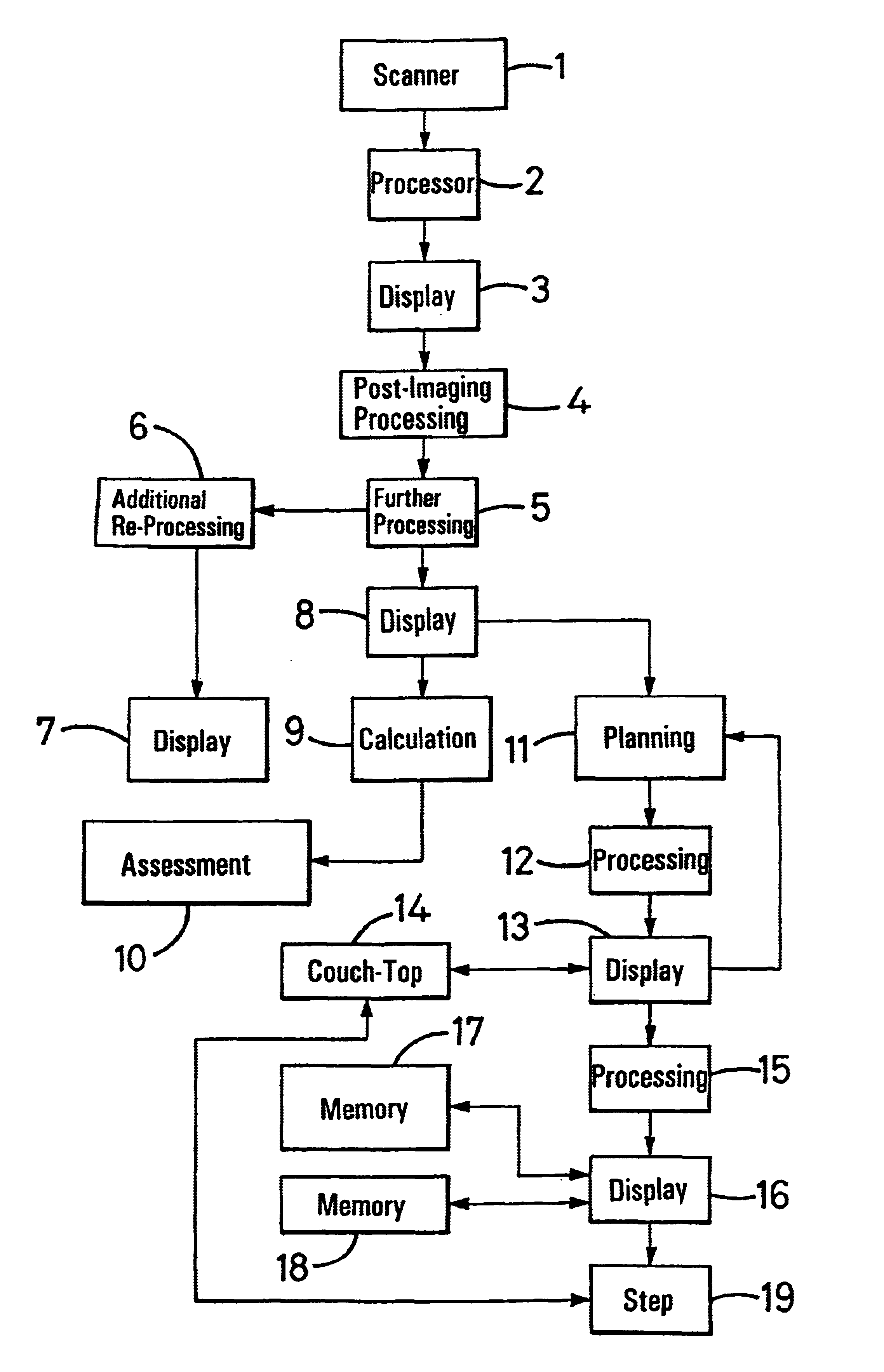
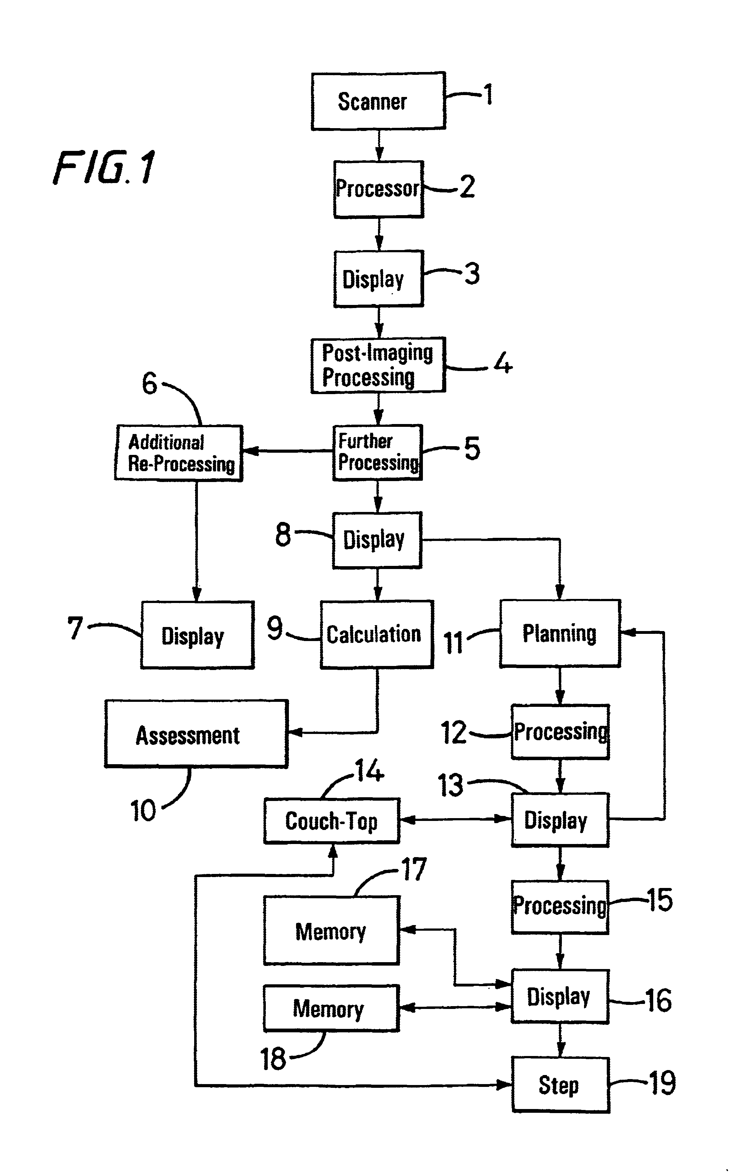
[0016]The method and system to be described with reference to FIG. 1 utilise MR scanning for medical diagnostic and treatment-planning purposes. In principle and in the general techniques described, the method and system of the invention can be used in other applications of MR scanning and also in circumstances where other scanning techniques are utilised. Furthermore, although both structure and function are represented by discrete ‘boxes’1 to 19 in FIG. 1, the method and system are to a substantial extent manifest in programmed digital data-processing operations.

[0017]Referring to FIG. 1, data derived in accordance with conventional operation of an MR scanner 1 is processed for imaging purposes within a processor 2. The output of the processor 2 is used to provide a display 3, and from this is subject to post-imaging processing 4. The post-imaging processing 4 includes the facility for selecting a region of the display 3 for more-detailed and closer inspection.

[0018]To the extent ...


PUM


Abstract

A de-convolution process is applied to an MR, CT or other image (25) of a scanned-object (23) to derive the point-spread function (22′) at an object-edge and to pin-point from the mid-point of its full-width-half-maximum FWHM, the location (30) of the true image-edge. With the object-image (25′) overlying the PSF function (22′) in the de-convolution space, sub-pixels which follow location (30) are transferred to before it to re-construct the image-edge (25′) for sharper conformity to the object-edge (23). Sharp definition of image-contour (37) facilitates accurate determination of area and volume of image profiles (35) and their segmentation. The accurate image-edge definition enables viable correction of geometrical distortion in stand-alone MR diagnosis and treatment planning.

Description

FIELD OF THE INVENTION[0001]This invention relates to imaging and in particular to methods and systems for image enhancement.BACKGROUND OF THE INVENTION[0002]Imaging involves transfer from the object domain into the image domain, but owing to limiting factors such as the finite size of energy source, detector size, sampling frequency, display density, software filter function, and possibly partial-volume effects experienced with some imagers, an infinitely fine delta function in the object domain cannot be faithfully reproduced in the image domain. Instead, a smeared-out image, or point-spread function (PSF), is observed. Similarly, an infinitely sharp edge-response function (ERF) in the object domain becomes a smeared-out ERF in the image domain. The smearing effect becomes more intense as the adjacent ERFs of discontinuities or contrast profiles get closer to each other.[0003]It is an object of the present invention to provide a method and system by which the above problem can be ...

Claims


Application Information

Patent Timeline
IPC IPC(8): G06T5/00A61B5/055A61B6/03A61B8/00G06T1/00G06T5/30G06T7/60
CPCG06T7/0083G06T2207/10072G06T2207/30016G06T7/12
Inventor CHUI, KUI MING
Owner CHUI KUI MING
Why Eureka
Try Eureka