
Remote caller identification telephone system and method with internet retrieval

Inactive Publication Date: 2005-08-09
RPX CLEARINGHOUSE
View PDF8 Cites 71 Cited by
  • Summary
  • Abstract
  • Description
  • Claims
  • Application Information

AI Technical Summary

Benefits of technology

[0006]It would be desirable to provide a method and system for caller identification, where a subscriber would be able to access information about a caller even if the caller hung up before leaving a voice mail message. It would further be desirable to provide a method and system for accessing the caller identifying information remotely, so that a subscriber may access the information from a remote phone or via the internet, and need not be at the subscriber's phone to access the caller identifying information. It would also be desirable to provide a method and system for caller identification, where a subscriber would not incur long distance charges when accessing information about a caller.
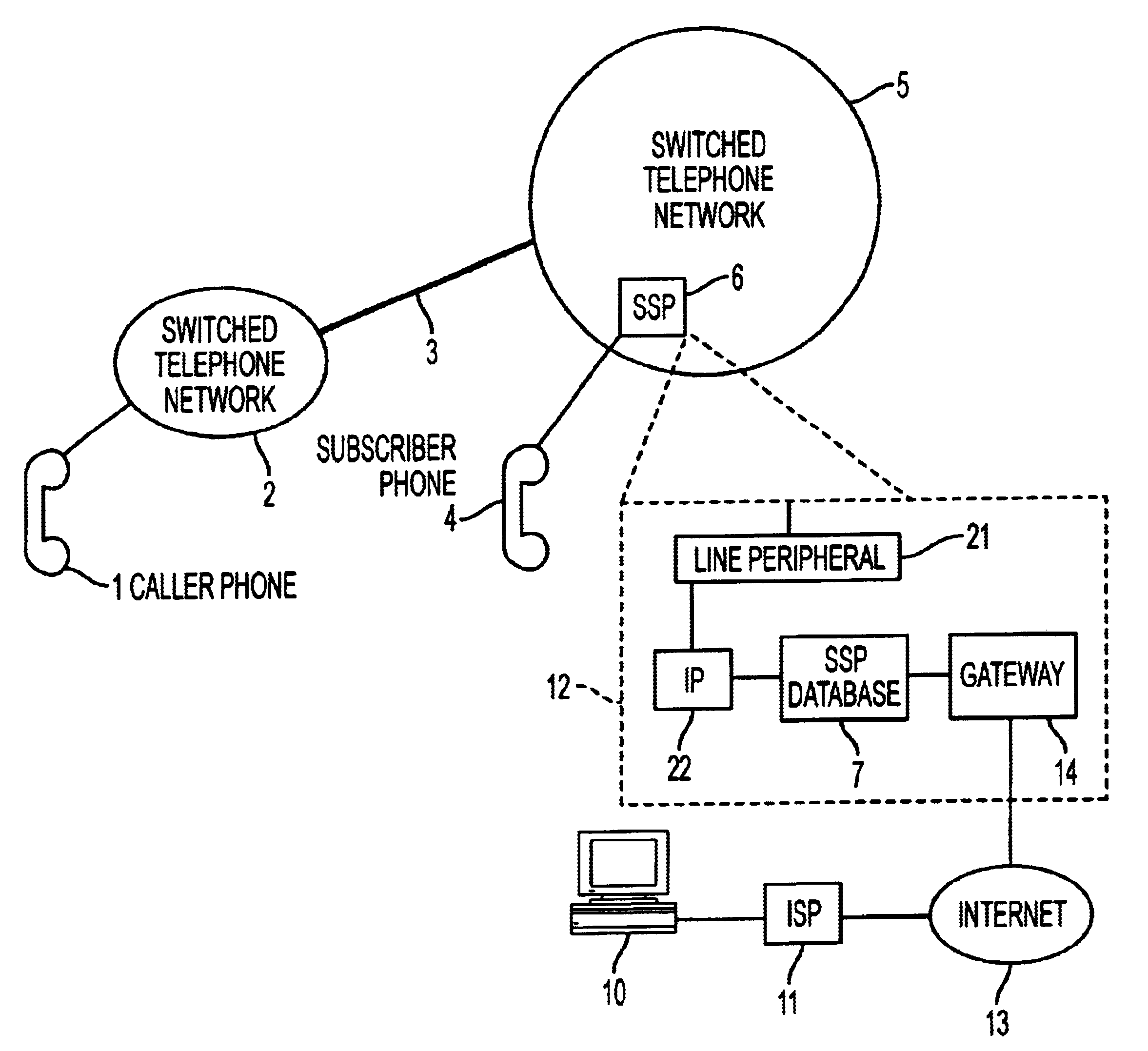
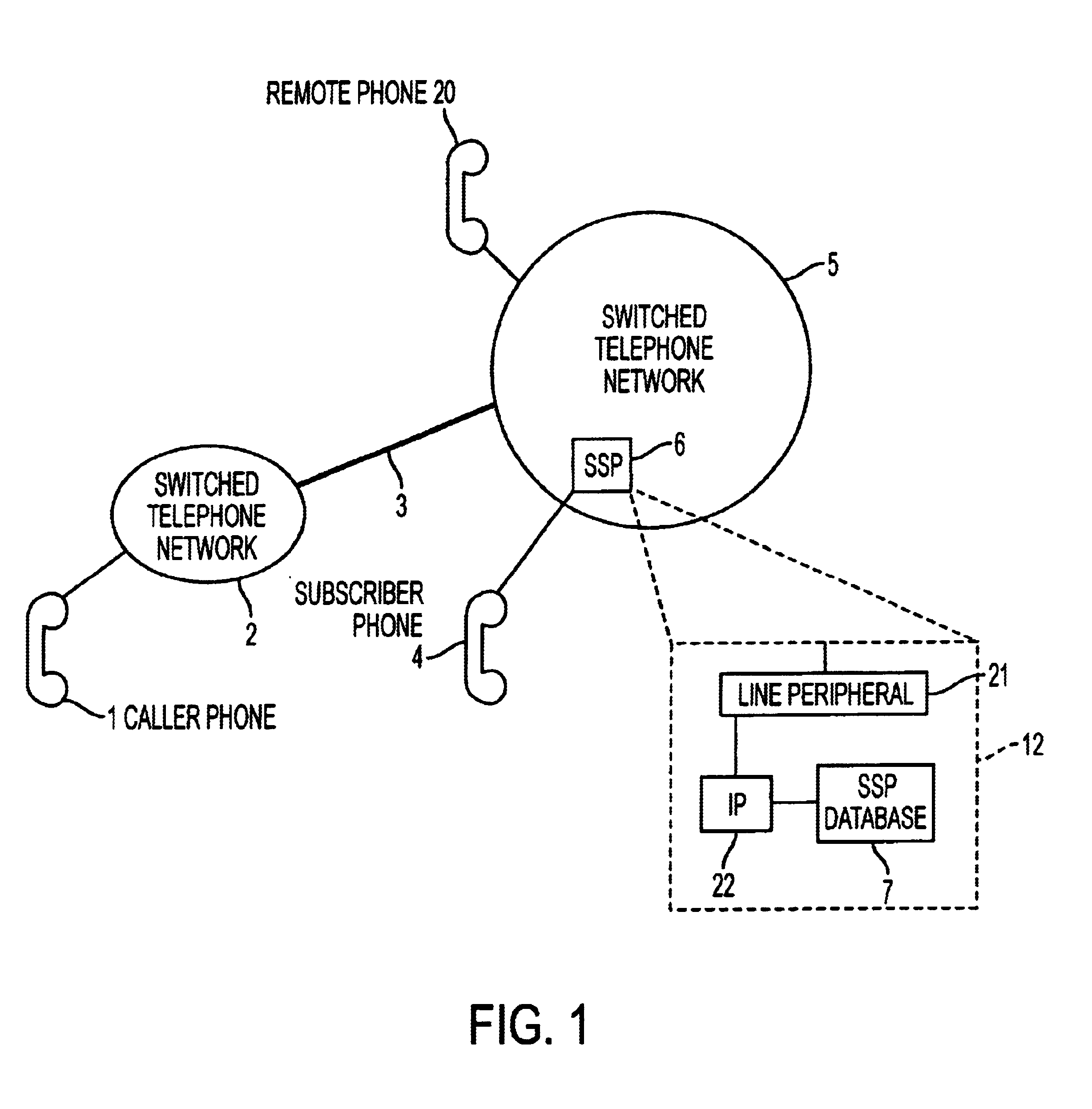
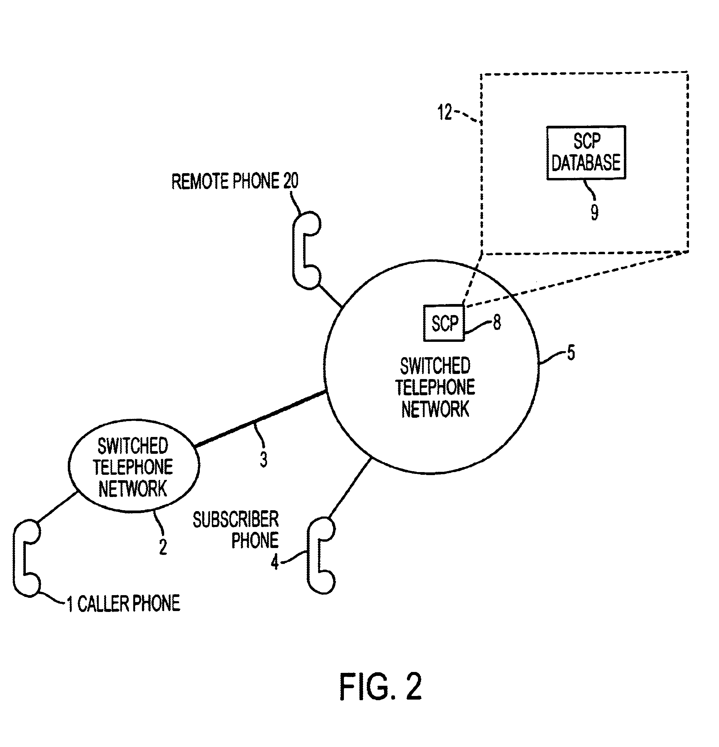
[0007]According to an embodiment of the invention, a data logging unit within a switched telephone network is provided. A subscriber phone is connected to the switched telephone network which contains the data logging unit. When a call is made to the subscriber phone, the data logging unit stores caller identifying information about the call. A subscriber may retrieve the caller identifying information from the data logging unit by accessing the data logging unit via a network such as the internet or via a remote phone. Because the caller identifying information is logged upon a call to the subscriber phone, the information is logged even if the caller subsequently hangs up before leaving a message on voice mail, or if the caller receives a busy signal. Also, the subscriber may retrieve the caller identifying information remotely without being near the subscriber phone. If the caller identifying information is retrieved via the internet, long distance charges may be avoided. The data logging unit may be implemented in a number of ways, including providing a data base local to a Service Signaling Point, in a Service Control Point, or in stand alone Customer Premises Equipment.

Problems solved by technology

However, if the caller hangs up before leaving a voice mail message, the phone user will not be able to identify that caller.
Often a caller is unwilling to wait until the phone user's greeting message ends to leave a message and will hang up.
Alternatively, the caller may simply not leave enough information in the caller's voice mail message for the phone user to identify the caller, and the phone user will then have little way of identifying the caller and returning a call to the caller.
Furthermore, if the phone user is accessing the VMS from outside the local calling area, the user may incur long distance charges.
However, it is often inconvenient for a phone user to return to his home or office to determine who has called.

Method used


Image

  • Remote caller identification telephone system and method with internet retrieval
  • Remote caller identification telephone system and method with internet retrieval
  • Remote caller identification telephone system and method with internet retrieval

Examples


first embodiment

[0022]The caller identification information is transferred to a subscriber switched telephone network 5 via line 3. Line 3 can be any interconnection medium capable of conveying or transmitting caller identifying information. Line 3 may be, for example, a Common Channel Signaling System no. 7 (CCS7) trunk. Alternatively, line 3 may be a wireless link, or a link through networks other than the switched telephone networks 2 and 5. In this first embodiment, the caller identifying information may be logged by storing the caller identifying information in a data logging unit 12 including a Service Signaling Point (SSP) based intelligent database 7 local to the SSP 6. The SSP 6 is within the subscriber switched telephone network 5. An SSP is a switch used within a switched telephone network and is typically the closest switch to the end user. In this case the closest switch to the end user would be the switch closest to the subscriber phone 4. The database 7 of the SSP is physically imple...

second embodiment

[0027]In this second embodiment the caller identifying information is logged in a data logging unit 12 including a Service Control Point (SCP) based intelligent database 9 in the SCP 8. An SCP is a type of switch which contains a database, which in an Advanced Intelligent Network (AIN), provides services to the SSPs, such as Call Display. The database of the SCP of this invention may be physically implemented using a storage medium, for example, a hard disk for data storage.

[0028]As with the first embodiment, the subscriber may retrieve caller identifying information simply by calling in via a remote phone 20. For example, the subscriber would call a number for the caller identifying information retrieval service to access the caller identifying data. Also in a similar fashion to the first embodiment, once the subscriber has called the information retrieval service, and provided a subscriber password via the remote phone 20 to be allowed to gain access to the caller identifying info...

third embodiment

[0032]FIG. 3B is another implementation of the In this implementation, however, subscriber phones 41a and 41b are connected to the SSP via a Private Branch Exchange (PBX) 40. A data logging unit 12, similar to that of the implementation of FIG. 3A, is connected to the PBX for logging calls to the subscriber phones 41a and 41b. A subscriber may retrieve caller identifying information directly from the data logging unit using the keypad and display, for example. Alternatively, the subscriber may call into the PBX to retrieve caller identifying information.

[0033]The first through third embodiments detail retrieving caller identifying information via a remote phone 20. This invention is not limited to retrieval via a telephone. A subscriber may retrieve the caller identifying information via any telephonic device. Telephonic device means a device which may access the identifying information retrieval service. For example, the telephonic device may resemble a pager more than a telephone...


PUM


Abstract

A remote caller identification system with data logging and retrieval features including a data logging unit which logs caller identifying information from incoming calls from a caller to a subscriber phone connected to a switched telephone network. A subscriber may subsequently retrieve the caller identifying information from the data logging unit via a remote phone or via the internet. The system has at least three possible implementations. In one implementation, the caller identifying information is stored in a Service Signaling Point database. In a second implementation, the caller identifying information is stored in a Service Control Point database. In the third implementation, the caller identifying information is stored in a database in a storage and retrieval device of a stand alone Customer Premises Equipment. A caller retrieving the caller identification information is prompted to input a password and with a menu to review or edit the caller identifying information.

Description

RELATED APPLICATIONS[0001]This application is related to application entitled “REMOTE CALLER IDENTIFICATION TELEPHONE SYSTEM AND METHOD”, Ser. No. 09 / 258,405, filed Feb. 26, 1999.BACKGROUND OF THE INVENTION[0002]This invention relates to a telephone system and method which allows a subscriber to remotely identify calls to the subscriber's phones.[0003]The ability to remotely identify phone calls placed to one's home or business is of increasing importance for allowing people the mobility to work from both home and business, and to travel while still keeping in touch with callers to home or business. Currently a phone user can remotely identify calls to his phone if the phone user subscribes to a voice mail system (VMS) service and has a voice mail account. If callers have called and left voice mail messages, the user may listen to these messages by placing a call to the voice mail service and then accessing the messages. Typically, the phone user accesses messages by listening to pr...

Claims


Application Information

Patent Timeline
IPC IPC(8): H04M3/42
CPCH04M3/42034
Inventor CHEAITO, RAMZIOSMAN, GHASSANOSMAN, MARWAN
Owner RPX CLEARINGHOUSE
Learn More