Rotational-rate sensor
a sensor and rotational rate technology, applied in the field of rotational rate sensors, can solve the problems of low reliability of vibration gyro, difficult selection of device materials, and inability to adjust the rotational rate, and achieve the effect of high reliability
- Summary
- Abstract
- Description
- Claims
- Application Information
AI Technical Summary
Benefits of technology
Problems solved by technology
Method used
Image


Examples
first embodiment
[0036](First Embodiment)
[0037]First, a rotational-rate sensor according to a first embodiment of the present invention will be described.
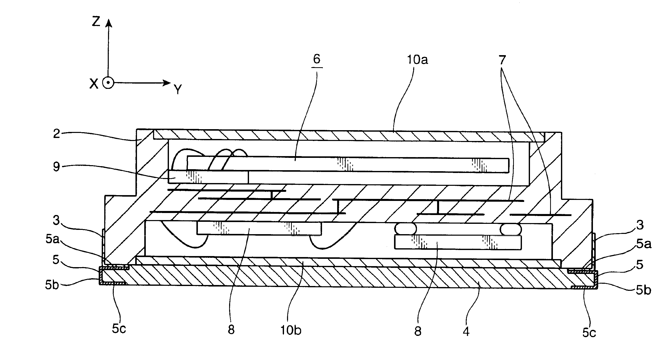
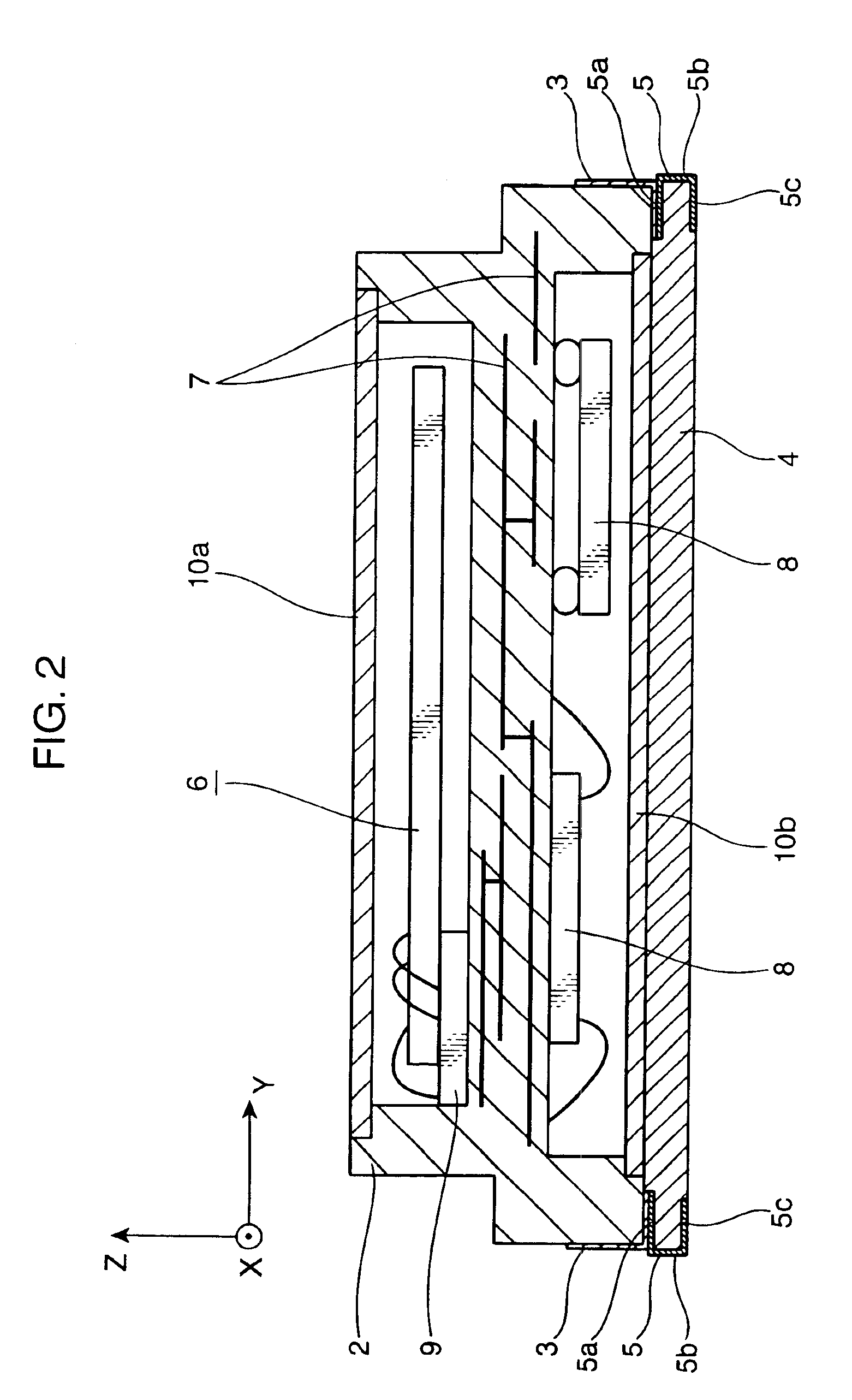
[0038]FIG. 1 is a perspective view of the rotational-rate sensor according to the first embodiment of the present invention. FIG. 2 is a sectional view of the rotational-rate sensor shown in FIG. 1, seen along an I—I line. Herein, an X-axis, a Y-axis and a Z-axis shown in FIG. 1 are the axes which shows the width direction, the longitudinal direction and the thickness direction of an airtight container 2, respectively.
[0039]A rotational-rate sensor 1 shown in FIG. 1 and FIG. 2 includes: the airtight container 2; pad electrodes 3; a silicone rubber 4; and a conductor portion 5.
[0040]The airtight container 2 has a rectangular-parallelepiped shape, and is made of resin such as ceramics and epoxy. The pad electrode 3 is made of gold or the like, and is placed at the lower part of the airtight container 2. It is used to supply power to the airtight rota...
second embodiment
[0077](Second Embodiment)
[0078]FIG. 14 is a perspective view of a rotational-rate sensor according to a second embodiment of the present invention. In FIG. 14, the parts which have the same configuration as those in FIG. 1 are given their identical reference numerals and characters. Hence, their detailed description is omitted, and thus, only different parts are described in detail.
[0079]In a rotational-rate sensor la shown in FIG. 14, a silicone rubber 4a is configured by a silicone rubber which extends in the Y-axis direction from the silicone rubber 4 shown in FIG. 1. It functions as the elastic body, in the same way as according to the first embodiment. A protrusion 50 is provided in the silicone rubber 4a. A hole 62 for positioning and storing the protrusion 50 is formed in a mounting substrate 60. In addition, a conductor portion 5a is provided in the silicone rubber 4a. The pad electrode 3 is connected via the conductor portion 5a to a conductor pattern 61 which is provided i...
third embodiment
[0081](Third Embodiment)
[0082]FIG. 15 is a perspective view of a rotational-rate sensor according to a third embodiment of the present invention. In FIG. 15, the parts which have the same configuration as those in FIG. 1 are given their identical reference numerals land characters. Hence, their detailed description is omitted, and thus, only different parts are described in detail.
[0083]In a rotational-rate sensor 1b shown in FIG. 15, a silicone rubber 70 is attached to the bottom surface of the airtight container 2. The silicone rubber 70 is glued to a mounting substrate 60a. The silicone rubber 70 is configured by a silicone rubber which is a columnar body whose section is circular. It functions as the elastic body, in the same way as according to the first embodiment. On the surface of the silicone rubber 70, a conductor portion 5b is provided which connects the pad electrode 3 that is made of gold or the like and an external electrode 61a that is provided in the mounting substra...
PUM
 Abstract
Description
Claims
Application Information
 - R&D
- Intellectual Property
- Life Sciences
- Materials
- Tech Scout
- Unparalleled Data Quality
- Higher Quality Content
- 60% Fewer Hallucinations
Browse by: Latest US Patents, China's latest patents, Technical Efficacy Thesaurus, Application Domain, Technology Topic, Popular Technical Reports.
© 2025 PatSnap. All rights reserved.Legal|Privacy policy|Modern Slavery Act Transparency Statement|Sitemap|About US| Contact US: help@patsnap.com