Eureka AIR delivers breakthrough ideas for toughest innovation challenges, trusted by R&D personnel around the world.

Method and device for separating samples from a liquid

a liquid separation and sample technology, applied in feed devices, liquid/fluent solid measurement, material testing goods, etc., can solve the problems of limited resolution of liquid quantity to be dispensed, limited reproducible dispensing of very small volumes in the nanoliter or even picoliter range, and limited hydrostatic pressure within a wide range. achieve economic and highly reproducible volume separation

Inactive Publication Date: 2005-08-09
TECAN TRADING AG
View PDF33 Cites 14 Cited by
  • Summary
  • Abstract
  • Description
  • Claims
  • Application Information

AI Technical Summary

Benefits of technology

[0011]An object of the present invention is to provide devices and methods that allow both economical and highly reproducible separation of volumes in the nanoliter to picoliter range.

Problems solved by technology

The droplet size thus limits the resolution of the quantity of liquid to be dispensed.
Such systems are relatively economical, but they have the disadvantage that the hydrostatic pressure can vary within a wide range.
The reproducible dispensing of very small volumes in the nanoliter or even picoliter range is impaired thereby.
The feed of the dispensing pump of this rather expensive and complex system is then regulated via a pressure sensor and an attached processing unit.

Method used


Image

  • Method and device for separating samples from a liquid
  • Method and device for separating samples from a liquid

Examples


first embodiment

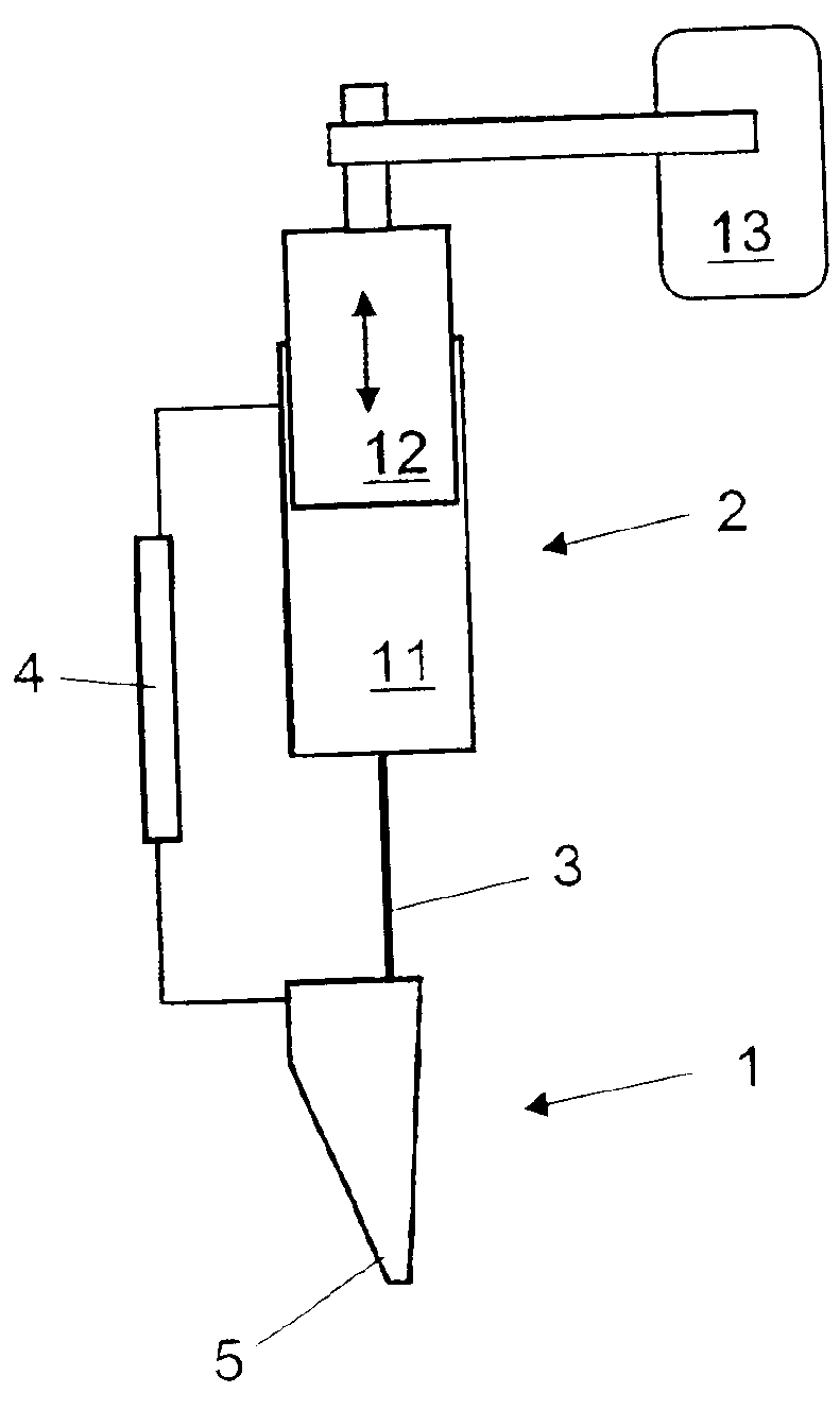
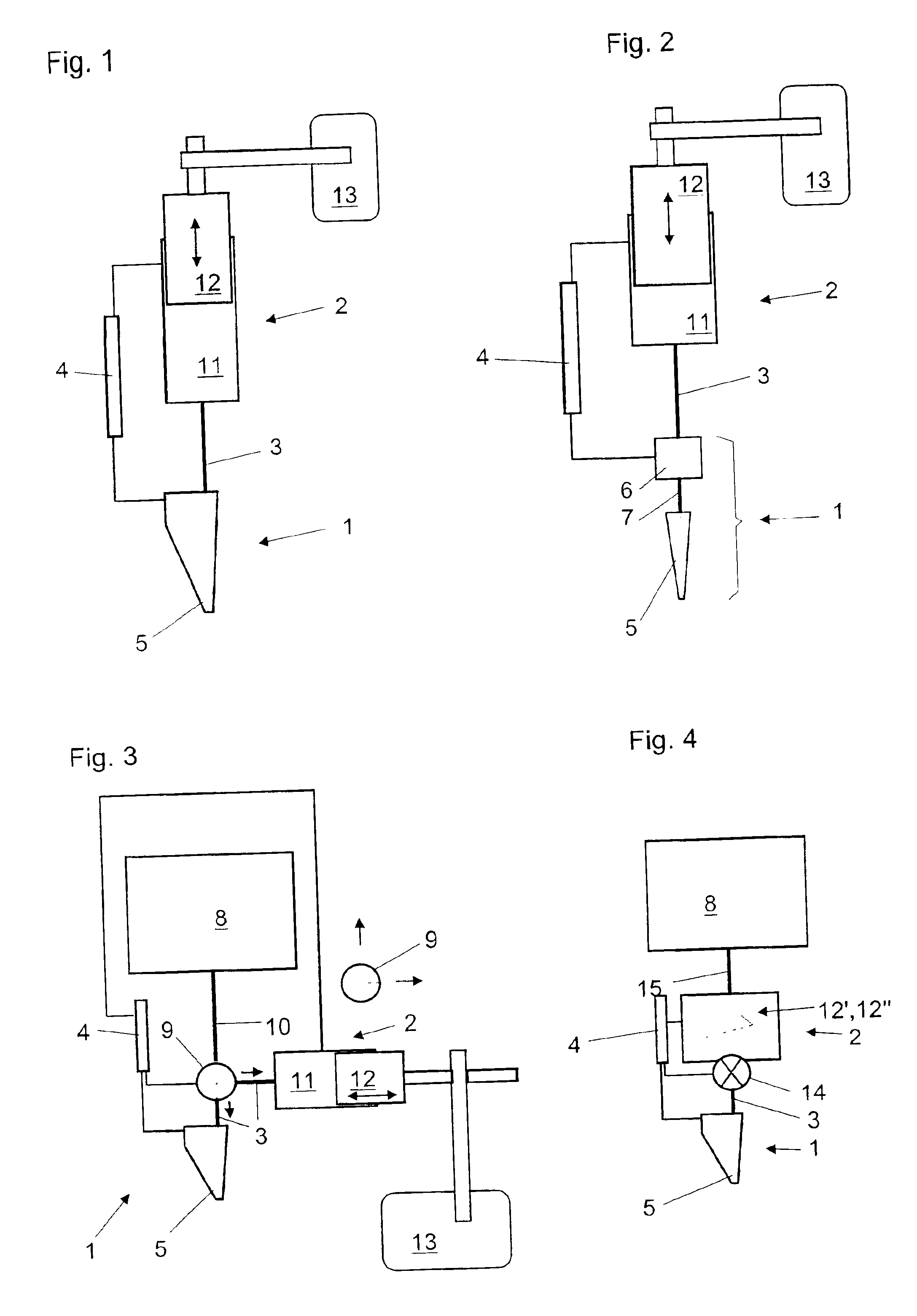
[0021]FIG. 1 shows a system for aspirating and / or dispensing liquid samples, in which microejection device 1 comprises an endpiece 5 implemented as a microejection pump. In this embodiment, a microejection device 1 implemented as a piezoelectric micropump is preferred.

second embodiment

[0022]FIG. 2 shows a system for aspirating and / or dispensing liquid samples in which microejection device 1 comprises an endpiece 5, implemented as a disposable pipette tip, a pulse generator 6, and tubing 7 which connects an endpiece 5 and pulse generator 6. The pulse generator, whose functional principle is known from, for example, U.S. Pat. No. 5,763,278, triggers pressure waves in tubing 7, which cause the liquid droplets to be driven out of endpiece 5—implemented in U.S. Pat. No. 5,763,278 as a needle.

third embodiment

[0023]FIG. 3 shows a system for aspirating and / or dispensing liquid samples in which microejection device 1 comprises an endpiece 5 implemented as a microejection pump. In this embodiment, a microejection device 1 in the form of a piezoelectric micropump is preferred. This embodiment additionally comprises a reservoir 8 and / or a three-way valve 9, with three-way valve 9 being positioned between pump 2 and reservoir 8. Reservoir 8 and three-way valve 9 and pump 2 are connected with one another via tubing 10. Notwithstanding the illustration in FIG. 3, the liquid transport can occur from microejection device 1 into pump 2 and from pump 2 in the direction of reservoir 8 via two separate valves (not illustrated in the Figure).

[0024]The first three embodiments share the feature that pump 2 is a piston pump that comprises a cylinder 11, a piston 12, and a drive 13. Among the many possible pumps for highly precise aspirating and dispensing of liquids, a commercially available device with ...


PUM


Abstract

System, method, and computer program product for synchronizing a system for aspirating and / or dispensing of liquid samples that includes a microejection device and a pump, which are connected with one another via tubing, wherein a computer is capable of being loaded with an activatable computer program product for synchronizing operation of the microejection device and the pump. Embodiments are characterized in that the loaded and activated computer program product, directs the computer to control and synchronize the system: (a) to actively define a sample volume and dispense the defined sample volume using the microejection device, which is filled with sample liquid; and (b) to track a part of the pump that conveys liquid around a value, dependent on the sample volume, which is defined and is actively dispensed only by the microejection device, to prevent excessive pressure differences in the microejection device, tubing, and pump.

Description

[0001]This application claims priority under 35 U.S.C. §119 to Swiss patent application no. 2000 2252 / 00, filed Nov. 17, 2000.FIELD OF THE INVENTION[0002]The present invention relates to a computer for synchronizing a system for aspirating and / or dispensing liquid samples that comprises a microejection device and a pump which are connected with one another via tubing, with this computer being implemented for loading an activatable computer program product for synchronizing the microejection device and pump. The present invention also concerns a corresponding system, method, and computer program product.BACKGROUND OF THE INVENTION[0003]It is known that droplets with a volume of more than 10 μl can be dispensed from the air very easily, since if the pipette is correctly manipulated, the droplets leave the pipette tip of their own accord. The droplet size is then determined by the physical properties of the sample liquid, such as surface tension or viscosity. The droplet size thus limi...

Claims


Application Information

Patent Timeline
IPC IPC(8): B01L11/00B01L3/02G01F25/00G01N35/10G01N37/00B01J4/02B01L99/00
CPCB01L3/021B01L3/0268G01F25/0092B01L99/00G01N35/10Y10T436/12G01N2035/1006G01N2035/1039B01L13/02
Inventor SICKINGER, ANSELMROMER, HANSPETERINGENHOVEN, NIKOLAUSKNECHT, URS
Owner TECAN TRADING AG
Why Eureka
Eureka Blog
Learn More