
Real time DSP load management system

a load management system and real-time technology, applied in the field of real-time dsp load management system, can solve the problems of physical limitations, one or more cpus may not be able to efficiently perform general system/application tasks, and achieve performance speeds of greater than 100 mhz, etc., to achieve the effect of enhancing the processing capabilities of an soc devi

Inactive Publication Date: 2005-08-02
REALCHIP
View PDF19 Cites 92 Cited by
  • Summary
  • Abstract
  • Description
  • Claims
  • Application Information

AI Technical Summary

Benefits of technology

[0015]It is an object of the present invention to provide a DSP load management system that enhances the processing capabilities of an SOC device.
[0016]It is another object of the present invention to provide a DSP load management system that enables parallel processing of data at high frequency from shared memory.

Problems solved by technology

Many applications such as high-speed communication products (VoIP, MoIP, wireless, imaging) require chip speeds that may be unattainable with separate IC components.
This is primarily due to the physical limitations of moving data from one chip to another, through bonding pads, wires, buses, etc.
As a consequence, the one or more CPUs may not be able to efficiently perform general system / application tasks since each request from the DSPs consumes tens or hundreds of CPU clock cycles.
It is also known that on a single board, performance speeds of greater than 100 MHz is quite difficult to achieve for DSPs with 16 bit capabilities.
This means that the CPU cannot perform all the functions for the multiple DSPs and MACs.
This method, however, requires a great deal of memory space and is often very costly and inefficient when implemented using a conventional CMOS logic process.
Alternatively, it can be implemented using an embedded DRAM process, but this process is also very costly.
Embeddable DSPs with 800 MHz to 2 GOPPS / s clocks are currently not available for such systems.
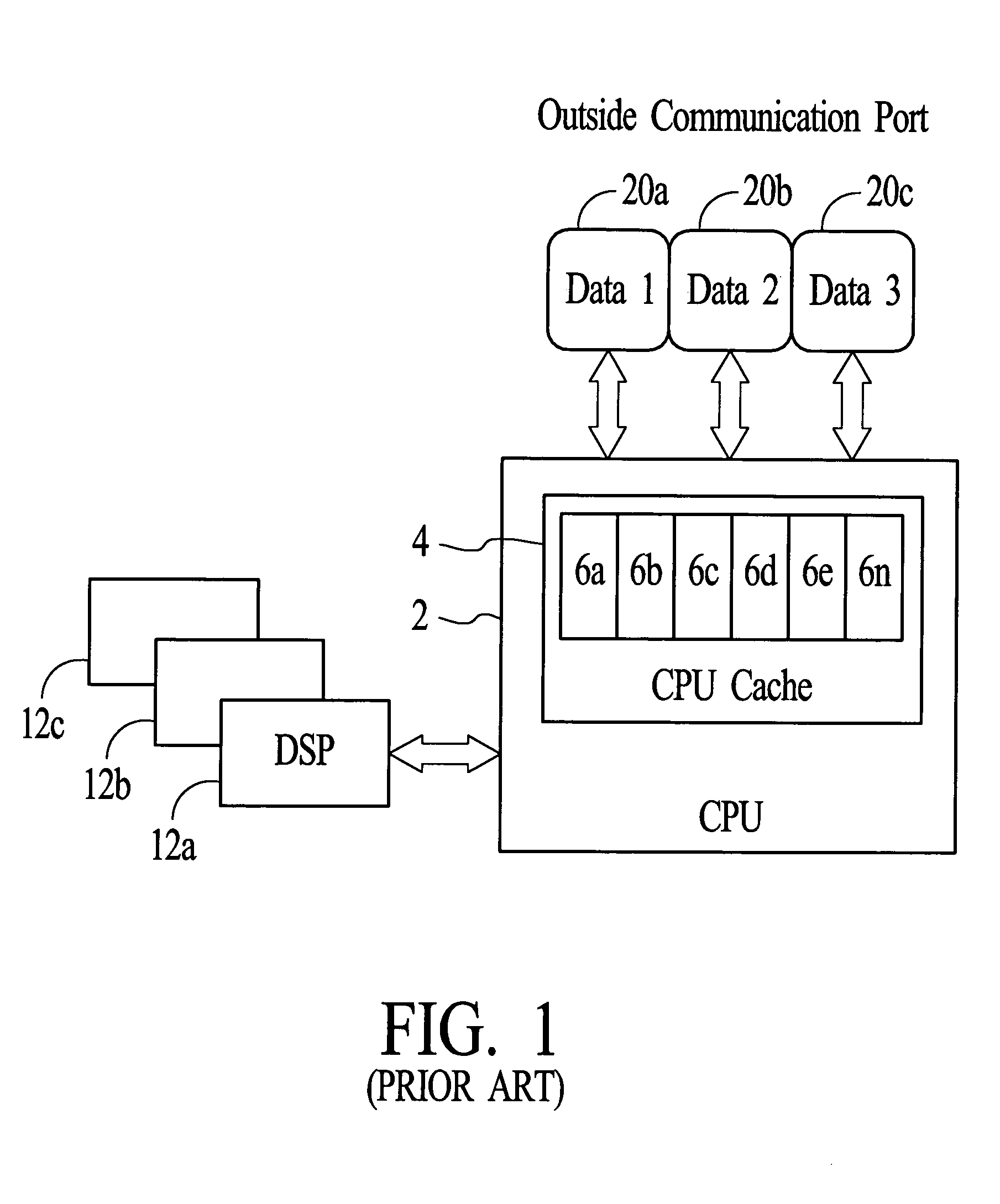
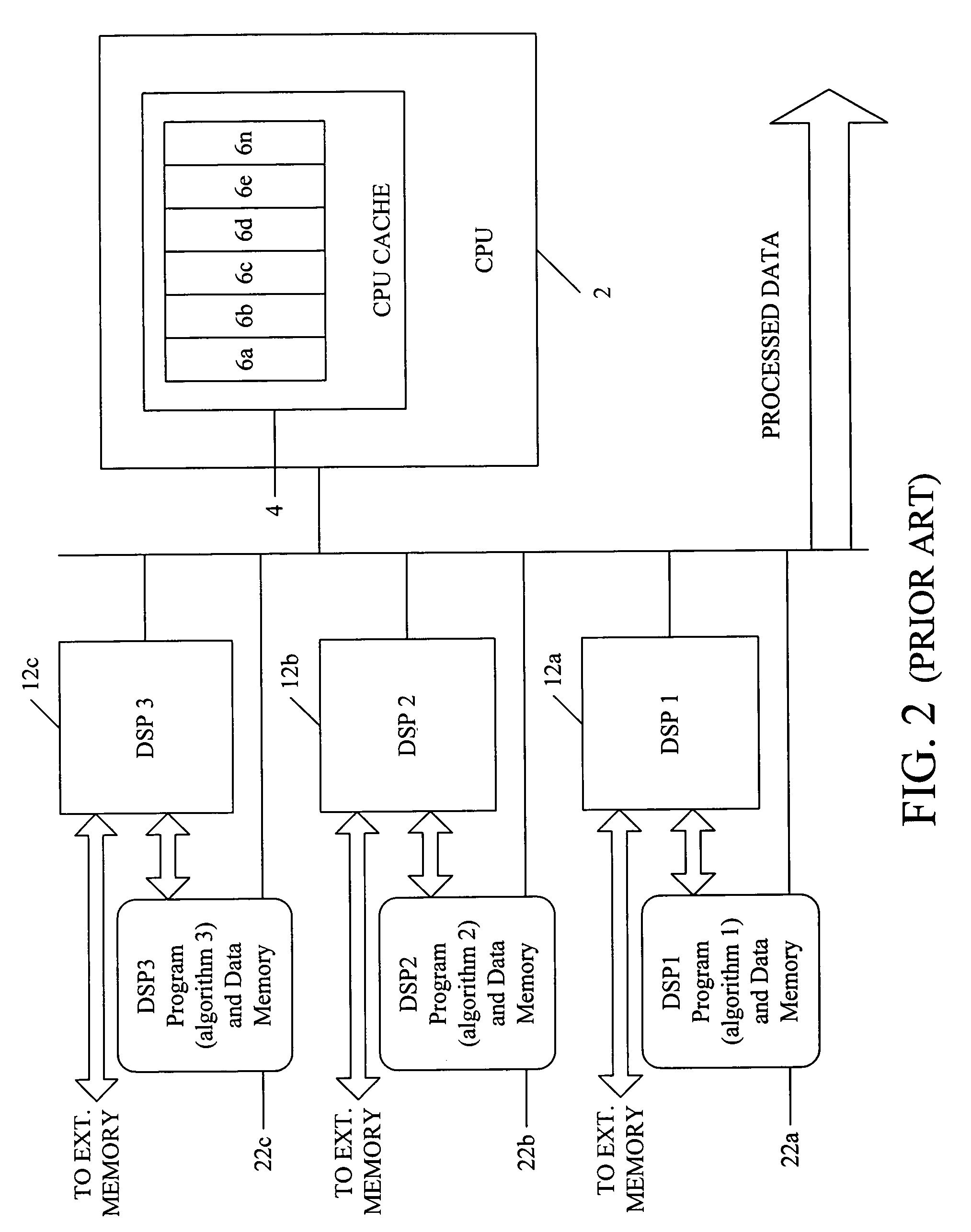
However, this schema will fail if the data is fast (i.e., imaging, fast communication ports such as T3 45 Mbps, etc.) and when the CPU 2 has to perform other application or system functions or when arbitration the memory reduces data throughput.
As can be appreciated, the conventional system is very limiting since switching algorithms can be time-consuming.
In addition, the conventional system is designed to only handle data with very slow rates.

Method used


Image

  • Real time DSP load management system
  • Real time DSP load management system
  • Real time DSP load management system

Examples


Embodiment Construction

[0056]The present invention will be described in greater detail, which may serve to further the understanding of the preferred embodiments of the present invention. As described elsewhere herein, various refinements and substitutions of the various embodiments are possible based on the principles and teachings herein.

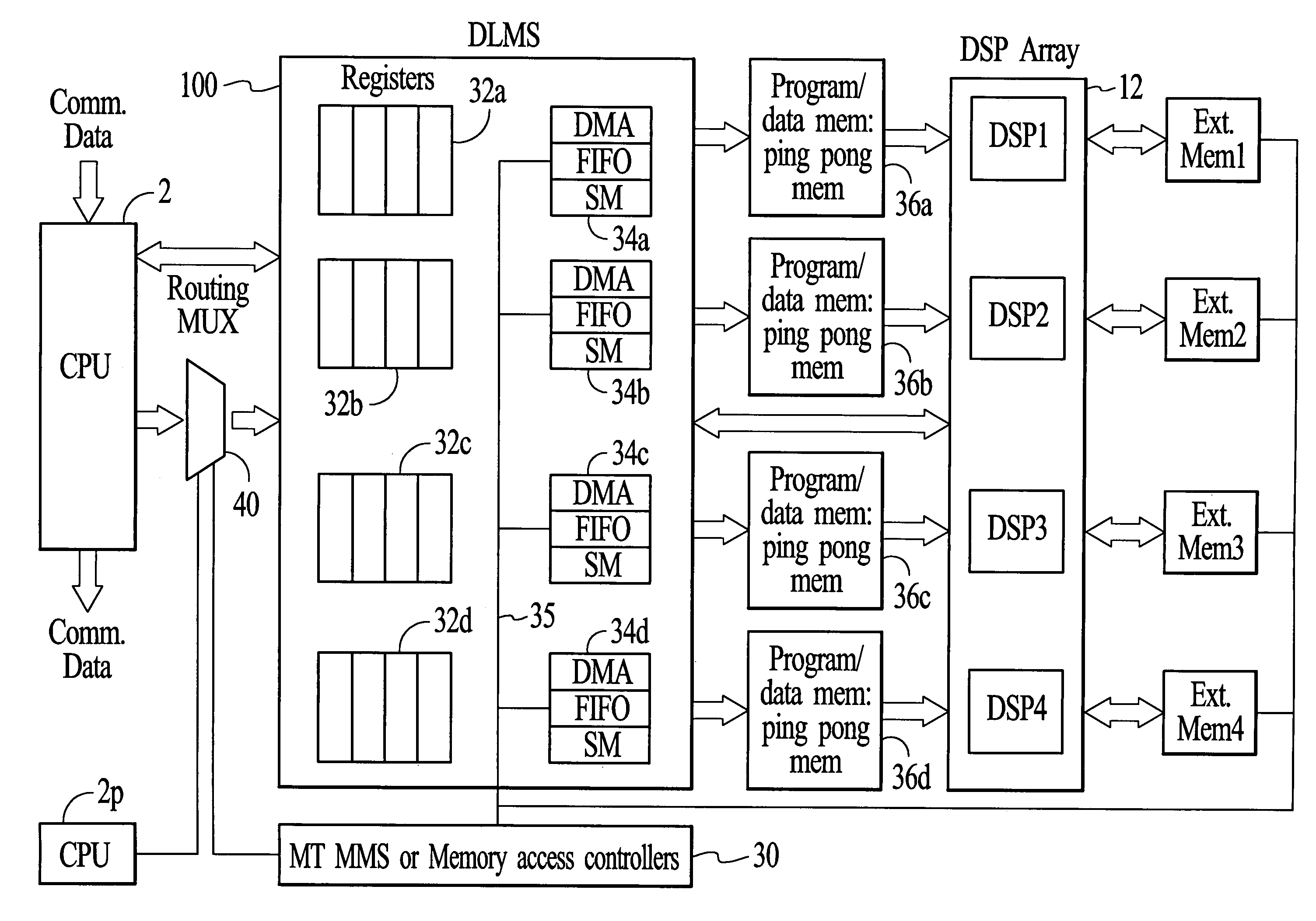
[0057]The preferred embodiments of the present invention will now be described with reference to FIGS. 3–18, wherein like components and steps are designated by like reference numerals throughout the various figures. Further, specific parameters such as algorithms, loads, speeds, data rates, and the like are provided herein, and are intended to be explanatory rather than limiting.

[0058]The present invention relates to a system and method that combines hardware and software functionalities to provide a DSP load management system (DLMS). The present invention allows a single chip to include one or more CPUs, a DLMS layer, and multiple DSPs. Each DSP can access an external...


PUM


Abstract

A highly intelligent DSP load management system is described herein for enhancing the processing capabilities of an SOC device. The DSP load management system enables parallel processing of data at high frequency and distributes, reads and writes data to several CPUs and / or DSPs in the same clock cycle. In addition, the DSP load management system provides forward looking real-time evaluation of arriving data and diverts tasks from one DSP to another, with short or zero latency. The DSP load management system is interfaced between one or more CPUs, one or more DSPs and / or a memory management system for enabling parallel processing of data at high frequency.

Description

FIELD OF THE INVENTION[0001]The present invention relates to a DSP load management system, and more particularly, to a system and method for enhancing the processing capabilities of a system on chip (SOC) device. The DSP load management system of the present invention enables parallel processing of data at high frequency. The present invention is further directed to a system and method for distributing, reading and writing data to several CPUs and / or DSPs simultaneously or in the same clock cycle. In addition, the DSP load management system provides forward-looking real-time evaluation of arriving data and an algorithm to optimizing loading for multiple DSPs before, during, and after algorithm switching operations.BACKGROUND OF THE INVENTION[0002]An SOC device has many advantages and benefits over a separate component integrated circuit (IC) device. For example, the separate IC device generally includes components that are connected to each other on a printed circuit board, whereas ...

Claims


Application Information

Patent Timeline
IPC IPC(8): G06F9/46G06F9/50
CPCG06F9/505G06F9/5088
Inventor ELABD, HAMMAM
Owner REALCHIP
Learn More